Richard001
Veteran Member
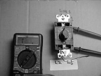
OK great, so now turn the dial so that there is some time on the timer. When you do that, load 1 should have a reading and load 2 should not.Yes ,Load 2 has a reading , load 1 no reading- open. thk/u
OK great, so now turn the dial so that there is some time on the timer. When you do that, load 1 should have a reading and load 2 should not.Yes ,Load 2 has a reading , load 1 no reading- open. thk/u
No, after turning the dial all stays the same ?OK great, so now turn the dial so that there is some time on the timer. When you do that, load 1 should have a reading and load 2 should not.
Lots of good input here and well thought , but i'm lost (reverse action switching ? ) SEG , GTS ignition, cube ignitions ?? I'm just a good valve lapper !! . Is the reverse action switching schematic drawing the one I should show my sparky buddy for help? thk/u. gus..Well according to this user instruction sheet I found on the internet, you have to wire the two line input terminals together for this to work as a spdt.
View attachment 710509
Note this bottom schematic, shows both lines wired together, then load1 or load2 will work for this application.
")
Hello; so which of the above posted wiring diagrams should i go by ? thk/u.Don't think of reversing or other bits that may confuse. From the common terminal either load will be on or off whether the timer is ticking or clicks off. Just use whichever either grounds your ignition to run or to stop. Connect in series to the magneto's primary wire if you can (point ign) or a gen's on/off switch (pointless ign)
If the timer is strictly mechanical no need to supply 120v or anything. Again just connect common to the engine (ground) or grounded term of a gen's on/off switch and whichever load terminal works to ground or not to shut 'er down. btw, betting you'll agree it's pretty simple once you've done it.
) has an on/off switch. By disconnecting the wires to it I could test which position is off or on then choose L1 or L2 and its line to get the same on/off function with the timer. Just two terminals to connect to vs the OEM switch. Wired in parallel with that would allow timed or normal operation. Wired in series with it they'd both have to be on but either could shut 'er down.OK to test we go; thanks for your timeDiagrams show a lot that you wouldn't use. My pump (not gen
So when the timer is 'on' (turn past 5 min) L1 & L2 should each reverse from 'open' to 'closed' accordingly. (easier to test from combined/jumpered 'common') Any SPDT switch would do the job, it's just that yours has the timer vs a handle/button and you don't need all its functions. Which load terminal will work for you is a matter of trial and error.
Nils - any progress to report ?OK to test we go; thanks for your time
Busy harvesting plums, going to try and pull the pump this week , will be sure to post a progress when time permitsNils - any progress to report ?
![pum].JPG](https://www.tractorbynet.com/forums/data/attachments/611/611335-0f661885aef0e25f6cf93945469b3f76.jpg "pum].JPG") .. thk/s
.. thk/s