Guess it's time to post more on my project and this will be mostly about the hoe assembly. Mine is the Case model 32 backhoe group. It will include the disassembly and all of the repairs and finally the reassembly and painting of all the groups contained in the model 32. Here is the first part of stripping it down:

I know this picture shows an earlier condition because you can tell the hood and tank are not painted and installed on the tractor, but I forgot to start taking pictures at the start of dismantling it all and I wanted to show you that I had tacked a temporary A-frame to the boom to keep it stable while I was working on the loader and tractor. So, the first thing I had to do was cut off the weld tacks and remove the bucket. That's where my crane came in real handy. After removing the bucket I was able to, along with the crane, lower the boom and crowd and by stretching it out, drop it enough to work on. You can see in the pictures that the crowd and bucket cylinders are painted, that is because they were the first thing I restored before bringing it inside the shop. So, that's one of the few things that I won't have to do before I put it back together, yaay!

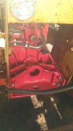
Of course this one shows just before lowering both stabilizers and removal from the rear of the tractor. I had also removed and rebuilt both right and left stabilizers before bringing the machine into the shop for start of restore. The problem was; most of the hoses, cylinders, and anything that contained fluid was leaking so bad I had to do those repairs before even moving it. Fluid was leaking out of the swing cylinders so bad that it left a steady stream right onto the shop floor. Every pin and bushing on the hoe was so worn that it would swing to and fro like it was dancing at a hoe-down, pun intended!

Here, you can see the removal of the crowd cylinder and I used my gambol that I fabricated for handling the loader arms. I've had to make or invent so many tools to make the project easier that I've lost count of their number. At the end of this project I'm going to spread them all out on my fab table and show you the number of tools that I've made. The one thing that was nice about this part was that I had pre-lubed all of the pins-bushings and hydraulic connections (JIC fittings), so they came apart easily. If you look close on the crowd (stick) plates you can see the fish plates that were welded for re-enforcement. Also, I will not be using the old boom or crowd, I found replacements and have had them for a long time now. They are in way better condition than these.

Got the pins out and the cylinder loose and ready for the next step. In this perspective you'll notice the fish plates that I talked about earlier. Also you can see the plastic JIC fitting plugs that are on the table, I screw in to keep the hoses that I leave attached from leaking fluid. Because of the condition of all of the backhoe pins and bushings, I will be machining both pins & bushings for most of the hoe. I will be using 1018 low carbon and 1045 medium carbon cold rolled steel, and 8620 alloy steel for pins. The bushings will all be machined out of DOM 1020 low carbon cold rolled steel. And in each instance I will use a picture and description with the exact metal that I used and why. Like I told you guys at the front of this project I'm not a professional mechanic or machinist, but because of my background and a lot of reading I'm trying to use the best guess estimate for all of this. If some of my processes turn into mistakes I'll be sure and post and explain to the best of my ability why it failed and what I'm going to do to correct it.

Got the hoses removed and capped and cylinder sling in place for removing the bucket cylinder. Got the pin removed (top pin is 1 3/4" diameter & the lower bucket pin is 1 1/2") so time to take it off. The actual bucket pins and bushings were the worst, but I think that is pretty normal, they get the most dirt, water, grit and such. I put a piece of pine on the floor to protect the concrete while it was sliding outward.

Now I'm picking the crowd (stick), and removed the pin, by the way the pivot pin for this is 2" diameter. This part will just turn into scrap metal. The hoses for both the crowd and bucket were replaced around 1999 or 2000. They were Caterpillar type, the kind that you can reuse the fittings and only replacing hose material. The guy who had them made up for me was the main shop foreman at Cashman Equipment here in Reno. They really are a tougher hose material and a layer or two more than standard made hydraulic hoses.

If you look closely at the high point of the boom where both hoses are draped over, you can see the serious amount of weld build up on both sides of the bosses and plates and you can see at the bottom left in the picture the 3/4" rod that was welded as re-enforcement to the boom. And take a look at that hard tube coming from the front of the boom cylinder, it's bent like a pretzel, that's not flex hose! I'm in the process of detaching the pins for that cylinder.

Got the cylinder loose and removing with a continuous sling. You can see the bent up hard tube better in this picture. The tube was never attached to the hoses correctly and got tangled up with the other hoses with their wound armor and bent the crap out of it. You kind of have to thread it out of the boom, lifting then moving back then lifting and so on. Got no idea what kind of trick it will be to re-install.

Finally out and hanging, I moved it down to the saw horses and cleaned it up and then put it on the fab table where I'll take it apart and re seal and pack it. You know, it was interesting to note that the piston rod on the cylinder was real nice condition, no scratches or dents, I think because it's always protected inside the boom.

I removed the boom pivot pin (which is 2" diameter) and craned it away from the tower. This too, will become scrap metal! Once the hoses are all disconnected it was real easy to handle the boom. Also I noticed that the pivot pin is special in that it had a welded flat on one end and threaded bore on the other. It's one of the many I'm going to have to make. I chose 2" dia. 8620 alloy round bar to replace the old worn out pin. It is weldable and machinable, and that's important and along with those characteristics it has high strength and good wear features.

In this perspective you can see all of the welded areas. They had welded cold rolled rod on each side of the boom and welded up each plate where it had cracked from the bosses to the edge, my putty knife is laying on top of each stiff back rod. The two hard tubes are no longer connected to hoses and are just setting there, it is not the position that they are in when connected, they lay on the bottom of the boom body.

Booms off and going to be set down out of the way.

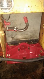
Finally got to the tower and just hoses to remove now. I took one of the swing cylinders off and put it up on the bench. Unbelievable how badly the pins and bushings were, it was no wonder that the boom and stick would move back and forth about 2 and half feet when I was operating it. Shucks, you just had to hunt the trench and drop it when you got close.

I've got the tower off and it too will go to the scrap heap. If you look closely near the top of the tower edges you can see some more rod welded as stiff backs or re enforcement. There were also fish plates formed and welded to the top sides of the tower. But since I won't be using this part again it won't matter how much it has been repaired. Also if you look at the pin with the shoulder on it nearest the black paint bucket, that is the bottom threaded pin that connects the tower to the hoe frame. It had wallowed out the self centering bushing (which I will show you in a later post) to the point that the tower was now riding on the bottom frame member which gouged out and dropped the boss probably 1/4". It was ground down into the boss weld.

Ok, here is the last picture of the disassembly. The hoe frame is now disconnected from the tractor and setting for the time being for a re-weld of the lower bushing boss and removal of the stabilizers. I made a tool to press out the old bushing in the up arm and also pressed out the lower self aligning bushing. I removed the valve body that was bolted to the inside frame, and almost took my arm off in the process. That valve body is all cast and it's pretty heavy. I'll probably tip the frame forward with my crane after the stabilizers are removed to make it easier to re-install the valve body.