Starting my bridge!!

   / Starting my bridge!!
  • Thread Starter
#121  
What weekend do you guys wanna come down and play??:)


No progress will be made this weekend.

Family voted to stay at “home” due to weather (cold and crappy here and at the farm) and the 1000 things that can/should be done here.

Loving all the input/drawings/etc from you all.

I’ve come upon some 1” solid round shaft-approx 16 pieces about 7’ long.

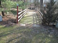
I may fab someway to space them in between my 3x3 tubes that are 30” apart and split that distance in half.
This should let me run my decking as 2x6 on the flat.

Gonna stir this in my brain and see what I come up with.

Back of my truck is filled with drops from a job I did this week

Piece of 8” c-channel about 8’ long
Couple 6’ chunks of 4x6x3/8 angle
Small pieces of 4x4x1/4 tube
20’ piece of 3x3x3/16 angle

My shop manager doesn’t want any of it to be sent back!!

Warehouse is full
 
   / Starting my bridge!! #122  
I really wanted to comment as soon as I saw this post, but I made sure to read the whole thread all the way through first.

I understand why you're building this the way your are. You're a good welder and have access to free materials. Makes sense. I won't argue with your design. Others more knowledgeable than I have already rung in on that. And time will prove it out one way or the other.

My only question is whether or not it would have been feasible and/or advantageous to put a culvert pipe in there and fill gravel and dirt over it? Just guessing maybe a one 2', a 3', or two 2' culverts? Just asking. Maybe the pipe is too expensive. Maybe the span is too far.

Best of luck with it. Looking forward to more updates and photos!

Bill
I put a 5 ft. Culvert in my creek, spent a day working on the thing. A week later, We got one of those hundred-year storms. Six inches of rain in around 10 hours. The culvert was completely washed out and moved about 50 ft. down stream.

Normally the creek is a 4ft. wide stream with a small trickle of water with some deeper holes for the minnows and crawdads. It really gets mean with heavy rain. but this was phenomenal. Pulled the culvert and made a ford.
 
   / Starting my bridge!! #123  
A pier is my last resort
I realize that you do not want a post mid-span , but looking at your other pictures you do have a post mid-span on one of your other bridges. Has it caused you any problems? Are those bridges over the same creek as your new bridge?
 
   / Starting my bridge!!
  • Thread Starter
#124  
I realize that you do not want a post mid-span , but looking at your other pictures you do have a post mid-span on one of your other bridges. Has it caused you any problems? Are those bridges over the same creek as your new bridge?
The one bridge with the pier is a different creek.
Problems…..mostly leaves/branches/etc. A couple big logs.

I’m trying to build with no pier.

If this all fails….pier it is!
 
   / Starting my bridge!! #125  
Basically the same thing as rigging.

Lifting chains and straps get derated when on an angle.

But I think your formula is sound for calculating tension for the example you give....like the car pulling on a cable tethered to anchors.

But I think why your numbers come up so much higher than mine.....is this isn't a freely flexing structure. You cannot discount the ability of the 2x6 itself to resist the load applied. Your formula of whatever weight being applied being a 10x or 15x factor in regards to tension is totally negating the strength of the main beam.
Definitely, this is to account for additional load.

If you're getting 5/8" deflection from 3000#, and your steel is basically rated for 5/8" deflection over 20' (240"/360 = 0.666), and you want to be able to put 6000# total on the bridge, you probably just need enough tension rod to hold the extra 3000" (once again, I'm not an engineer).

Personally, I'd spec out the tension rods to be capable of "holding" the entire load you want to put on the bridge and probably a bit more; in addition, I'd jack up the middle of the bridge a little bit so that when the rods are welded on, they immediately get some tension just from the empty bridge - effectively they're pretensioned a bit. If you have big enough rod to take it, you'd get a less bouncy bridge as a result.
 
   / Starting my bridge!! #126  
I've been following these but haven't said much yet. Ning's calculations make perfect sense for the tension on the rod, assuming a specific deflection of the blue rod. But as LD1 pointed out, the loading characteristics of this are far more complex. So if the bridge deflects X in the middle, Ning's math on the tension in the rod will be generally correct. That is one important factor as you do not want to exceed the yield strength of the rod itself and you sure need to run that calc before you commit. BUT....

The bigger problem here is the materials. Yes I get the free aspect. But 1/8" wall is barely there from a structural viewpoint and attaching any point loads to it is asking for it to buckle or tear out locally. At the very least I would want to add on plates to the tube where the tension rods and center stay would connect, and probably add them on the bottom and sides of the tube (maybe top too). I would want these to extend for a significant distance to spread the load out on that thin 1/8" skin. And I have no idea how to even calculate how long those should be. And thinking more about it, the same issue is going to be there at the end supports too. And then it still might buckle at the edge of the reinforcing plates under excessive loads...

Secondly I am strongly recommending that you avoid rebar for this use. Rebar can be sketchy on composition and can be unweldable or lead to a very brittle weld or HAZ. I would stick with regular A36 steel to ensure the welds have a fair chance of working and being ductile. 7018 would be a good choice if you are stick welding this. You don't want to find out that weld is brittle when your vehicle is at center span. This is where "free" could be very costly...

The thin wall is the part that makes me cringe the most especially with the heavy vehicles you are targeting. I think your biggest risk is going to be local buckling or crumpling of the skin from point type loads. I'm not talking about Euler column buckling here but just exceeding the yield strength of the steel in localized spots.

I am not saying this design will or won't work, as I am not a full structural engineer (had all the statics, dynamics, strength of materials, etc coursework in college, but the real world is not quite the same as the books and I do not practice in that area). But there are serious concerns due to the materials at hand. That along with the unconventional methods of trying to compensate for the thin material makes it questionable. The above are my suggestions based on what you have done and are planning but I'm not saying it is a great idea to keep going this route. Foot traffic and ATVs? Sure. Tractor or truck? Yikes.
 
   / Starting my bridge!!
  • Thread Starter
#127  
I've been following these but haven't said much yet. Ning's calculations make perfect sense for the tension on the rod, assuming a specific deflection of the blue rod. But as LD1 pointed out, the loading characteristics of this are far more complex. So if the bridge deflects X in the middle, Ning's math on the tension in the rod will be generally correct. That is one important factor as you do not want to exceed the yield strength of the rod itself and you sure need to run that calc before you commit. BUT....

The bigger problem here is the materials. Yes I get the free aspect. But 1/8" wall is barely there from a structural viewpoint and attaching any point loads to it is asking for it to buckle or tear out locally. At the very least I would want to add on plates to the tube where the tension rods and center stay would connect, and probably add them on the bottom and sides of the tube (maybe top too). I would want these to extend for a significant distance to spread the load out on that thin 1/8" skin. And I have no idea how to even calculate how long those should be. And thinking more about it, the same issue is going to be there at the end supports too. And then it still might buckle at the edge of the reinforcing plates under excessive loads...

Secondly I am strongly recommending that you avoid rebar for this use. Rebar can be sketchy on composition and can be unweldable or lead to a very brittle weld or HAZ. I would stick with regular A36 steel to ensure the welds have a fair chance of working and being ductile. 7018 would be a good choice if you are stick welding this. You don't want to find out that weld is brittle when your vehicle is at center span. This is where "free" could be very costly...

The thin wall is the part that makes me cringe the most especially with the heavy vehicles you are targeting. I think your biggest risk is going to be local buckling or crumpling of the skin from point type loads. I'm not talking about Euler column buckling here but just exceeding the yield strength of the steel in localized spots.

I am not saying this design will or won't work, as I am not a full structural engineer (had all the statics, dynamics, strength of materials, etc coursework in college, but the real world is not quite the same as the books and I do not practice in that area). But there are serious concerns due to the materials at hand. That along with the unconventional methods of trying to compensate for the thin material makes it questionable. The above are my suggestions based on what you have done and are planning but I'm not saying it is a great idea to keep going this route. Foot traffic and ATVs? Sure. Tractor or truck? Yikes.
You guys are all great when it comes to the info!!!

My 2x6 tubes (on the outboard ends) have a piece of 3x3x3/16 welded to them to carry the 3x3 cross tubes.
D3F67462-FF0A-4D14-989D-D1CC9040F788.jpeg

I can call my steel supplier about rod stock instead or rebar on Monday.

I can add additional plate reinforcements if need be.

Current thought process is to weld rod/rebar to 4x6x3/16 plates on ends.

Obviously if all this fails to be safe…..piers in the center of span will be installed
 
   / Starting my bridge!!
  • Thread Starter
#129  
Rebar is very weldable. Use it or rod which ever is cheapest
20’ stick of 5/8 is $13 I believe
3/4 isn’t much more

I’ve welded plenty of bar.
 
   / Starting my bridge!! #130  
Dstig1 had very similar thoughts to mine, he just said it better, mainly in regards to plates at connections and not using rebar. I have seen a lot of rebar handled at construction sites and when guys are carrying long sticks of it it just bows a lot and flops around. In tension that’s fine but in compression it just seems it would buckle easily. Square tubing, round tubing, I beams etc seem to be a better choice. It sounds like you got a lot of scrap a couple of days ago that could be used.
 
   / Starting my bridge!! #131  
I'm enjoying the comments from everyone with engineering knowledge. I'm a wood kind of guy, so it's interesting what can be done with metal. I've never seen or used 2x6 metal tubing, but I have bought and used some 2x4 metal tubing with 1/8's thick wall, and in my opinion, that was way too small to support any sort of load over a short distance. I'm struggling to believe that thinner metal, but taller, would be able to support anything spanning 20 feet.

If I was building something to span 20 feet out of wood, I would probably put posts in the ground at two locations to divide the span into thirds, and leave the middle of the creek free to flow. I would also have my beams under the tires for maximum strength. In this design, it appears that the tires will be over the joists, and not on the beams.

I like that concrete will be used to support the bridge. Not knowing the soil there, I would want the depth of the footings to be significant to avoid any settling or erosion from high water when it floods. Is 4 feet enough, or should it be 6 to 8 feet deep? Deeper would be better for the footings to be there 40 years from now. If it's not built to last decades, then why build it?
 
   / Starting my bridge!!
  • Thread Starter
#132  
Dstig1 had very similar thoughts to mine, he just said it better, mainly in regards to plates at connections and not using rebar. I have seen a lot of rebar handled at construction sites and when guys are carrying long sticks of it it just bows a lot and flops around. In tension that’s fine but in compression it just seems it would buckle easily. Square tubing, round tubing, I beams etc seem to be a better choice. It sounds like you got a lot of scrap a couple of days ago that could be used.
When the install is complete the rebar/rod stock will be in tension

B9C69899-42FB-49FD-8A61-8ED1073723BB.jpeg
 
   / Starting my bridge!!
  • Thread Starter
#133  
I'm enjoying the comments from everyone with engineering knowledge. I'm a wood kind of guy, so it's interesting what can be done with metal. I've never seen or used 2x6 metal tubing, but I have bought and used some 2x4 metal tubing with 1/8's thick wall, and in my opinion, that was way too small to support any sort of load over a short distance. I'm struggling to believe that thinner metal, but taller, would be able to support anything spanning 20 feet.

If I was building something to span 20 feet out of wood, I would probably put posts in the ground at two locations to divide the span into thirds, and leave the middle of the creek free to flow. I would also have my beams under the tires for maximum strength. In this design, it appears that the tires will be over the joists, and not on the beams.

I like that concrete will be used to support the bridge. Not knowing the soil there, I would want the depth of the footings to be significant to avoid any settling or erosion from high water when it floods. Is 4 feet enough, or should it be 6 to 8 feet deep? Deeper would be better for the footings to be there 40 years from now. If it's not built to last decades, then why build it?

I’ve got a pile of 2x5 tubes-probably 100 linear feet or more.
The 2x6 I only had 3 this length.

A door manufacturer uses them as a disposable “carriage” for their door assemblies.

The concrete abutments will be set up as a slab with rebar pins going down and some post holes filled with concrete at 2-3 locations.

The creek is a run off ditch from a 50 acre field next to my property. I’ve never seen it up to the top of the banks or see any evidence of it at the location the bridge is.
 
   / Starting my bridge!! #134  
We already know it will support a couple of atv’s. I personally wouldn’t worry to much about the abutments. It doesn’t sound like an essential bridge. What you have planned will probably work. If you get to carried away your bridge made from “free” material won’t be so free.
 
   / Starting my bridge!!
  • Thread Starter
#135  
We already know it will support a couple of atv’s. I personally wouldn’t worry to much about the abutments. It doesn’t sound like an essential bridge. What you have planned will probably work. If you get to carried away your bridge made from “free” material won’t be so free.

I’m willing to invest a bit of time/money if I learn something from this.
 
   / Starting my bridge!! #136  
You could certainly truss the top pretty darn good with 100' of 2x5 tube.
 
   / Starting my bridge!!
  • Thread Starter
#137  
You could certainly truss the top pretty darn good with 100' of 2x5 tube.
You sir……will be the death of me!!! :)

Those tubes have other uses.
 
   / Starting my bridge!! #138  
I’ve got a pile of 2x5 tubes-probably 100 linear feet or more.
The 2x6 I only had 3 this length.

A door manufacturer uses them as a disposable “carriage” for their door assemblies.

The concrete abutments will be set up as a slab with rebar pins going down and some post holes filled with concrete at 2-3 locations.

The creek is a run off ditch from a 50 acre field next to my property. I’ve never seen it up to the top of the banks or see any evidence of it at the location the bridge is.
Rebar pins going into the ground are cost and effort that give you little strength in return. If you want to drive pins use tubing not rods.
The pins will be in compression
 
   / Starting my bridge!! #140  
Thank you Doorman for posting. I'll have to look for your barn thread too. I never thought to look at this forum for projects. I'll be looking now. I'd like to see more pix of how the tubes are laid out.
I built a similar size bridge myself. It was one of my most fun projects ever. Hope it is for you too! A couple pix of the finished bridge. I wasn't intending to say so much, but only to encourage others to tackle what might at first seem hard. I built mine of treated wood: mostly 2x6x12's with a few 2x10 x12's. While I wouldn't hesitate to drive a car over it, if I could get it there, my goal was the Ford 8N I'm restoring. I had some free stuff. I salvaged about a 100 bolts which I used to bolt some 2x6's together. I did not bolt all of them, just those used to support the 8N width and my other smaller tractor width. It is sort of like a house floor under the 2x6 planks. I also had two I beams from my garage so those became my support ends on either side of the creek. I sunk 4x4 posts on the inside to hold in the beams which I just laid on a stone foundation. The main span was about 10-11 feet. But I extended both ends to take away the slope. I put one bolt in each of those, not two so that if it needed to rise for the water it would pivot. Only once that I know of did the water go that high. I watched the creek for a few years before this figuring out how high it would go. I used those 4x4 posts too to affix a roof truss to the center of the bridge for added support. I also looked at every bridge I came across while hiking various parks. After all this, I went on-line curious if there was any strength formulas. I guess that should have been my first step. But I was happy that what I did exceeded the expected weight. To relieve my erosion concern, (the bridge is in the middle of a horseshoe) I lined the creek edges with numerous 250 pound blocks that the local recycle shop had for free. But water is powerful. After several washed away, I then pounded rebar stakes through a few fortunate holes in the blocks and then bent over the ends.
 

Attachments

  • IMG_9996.JPG
    IMG_9996.JPG
    4.4 MB · Views: 191
  • IMG_9997.JPG
    IMG_9997.JPG
    3.5 MB · Views: 188

Tractor & Equipment Auctions

PALLETS OF HEAVYEQUIPMENT (A58214)
PALLETS OF...
2019 CATERPILLAR 259D3 SKID STEER (A60429)
2019 CATERPILLAR...
500 BBL FRAC TANK (A58214)
500 BBL FRAC TANK...
2014 Dodge Grand Caravan Van (A59231)
2014 Dodge Grand...
2025 CFG Industrial QK18R Mini Excavator (A59228)
2025 CFG...
Hays LT-1 Tender (A56438)
Hays LT-1 Tender...
 
Top