360* Rotating Back Blade Project

   / 360* Rotating Back Blade Project
  • Thread Starter
#21  
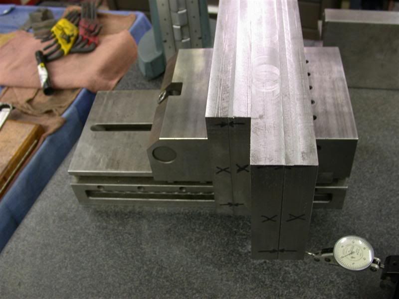
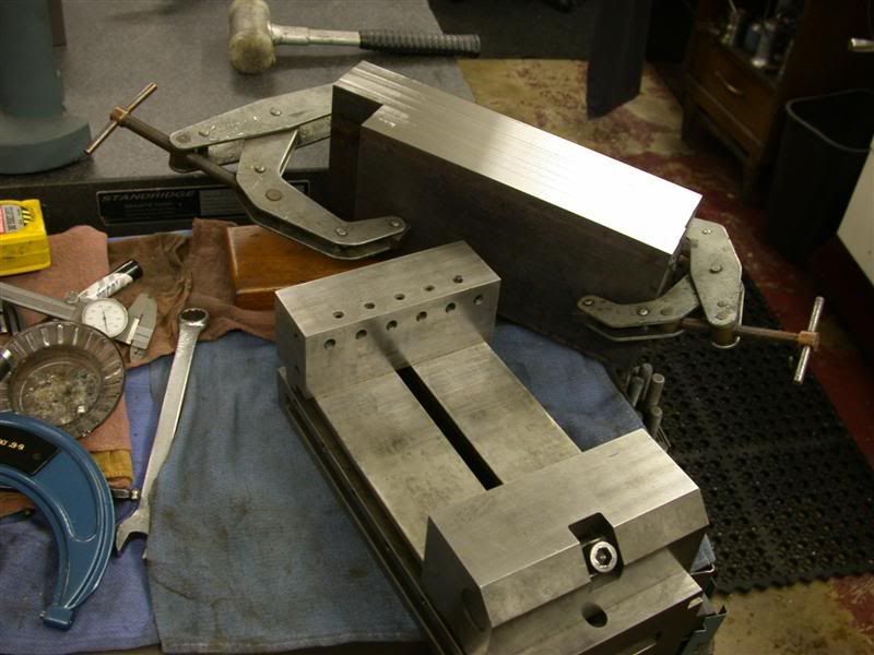
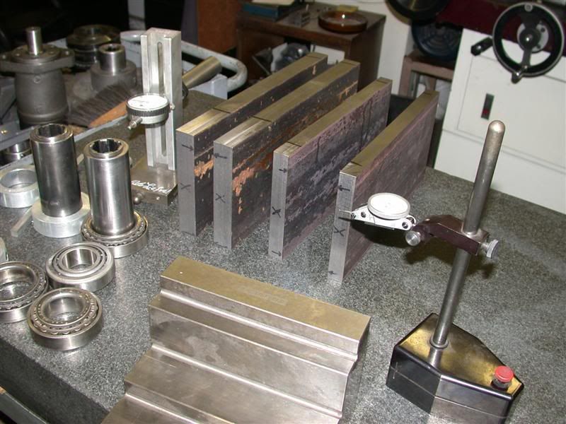
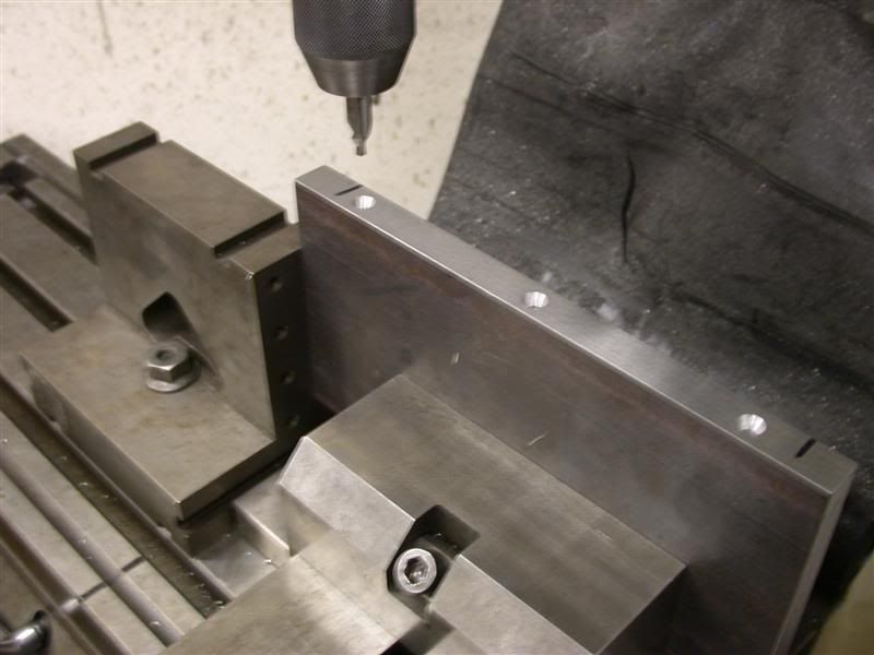
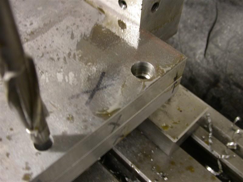
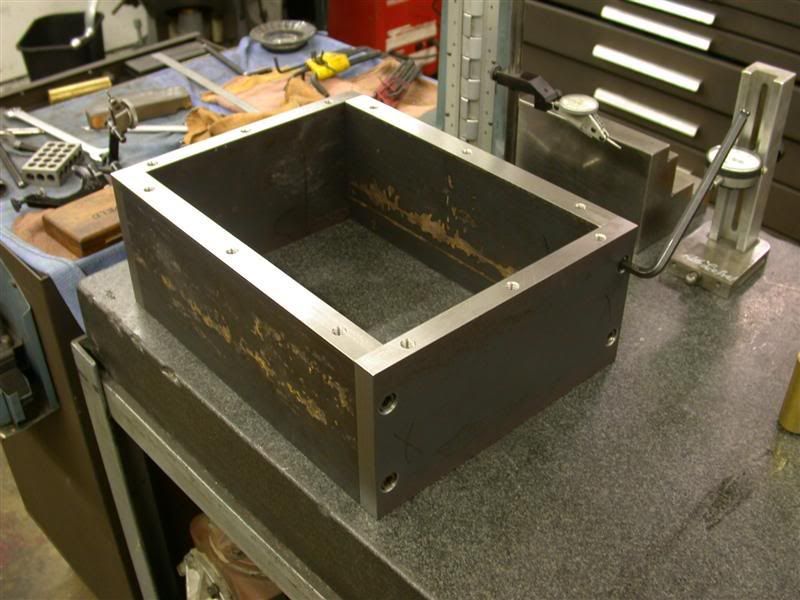
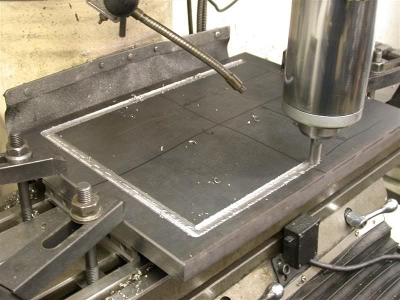
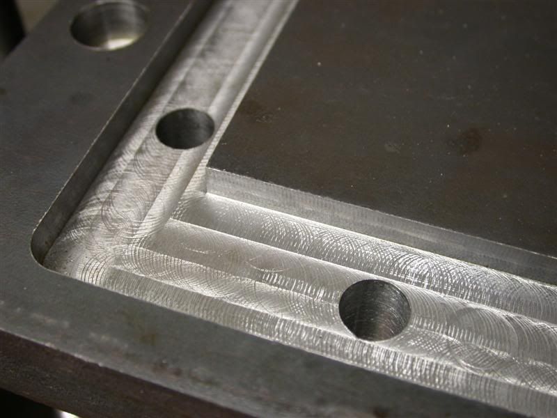
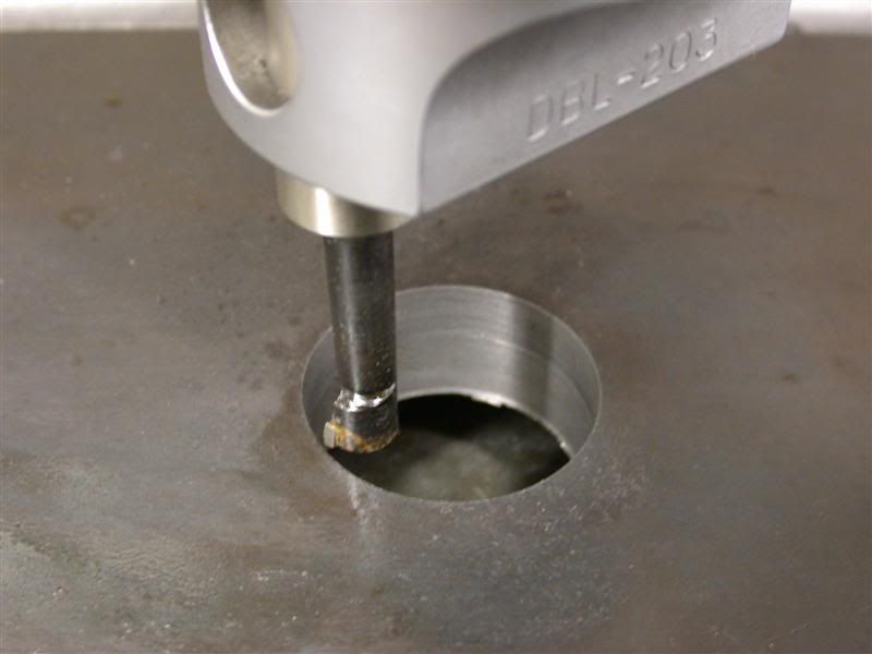
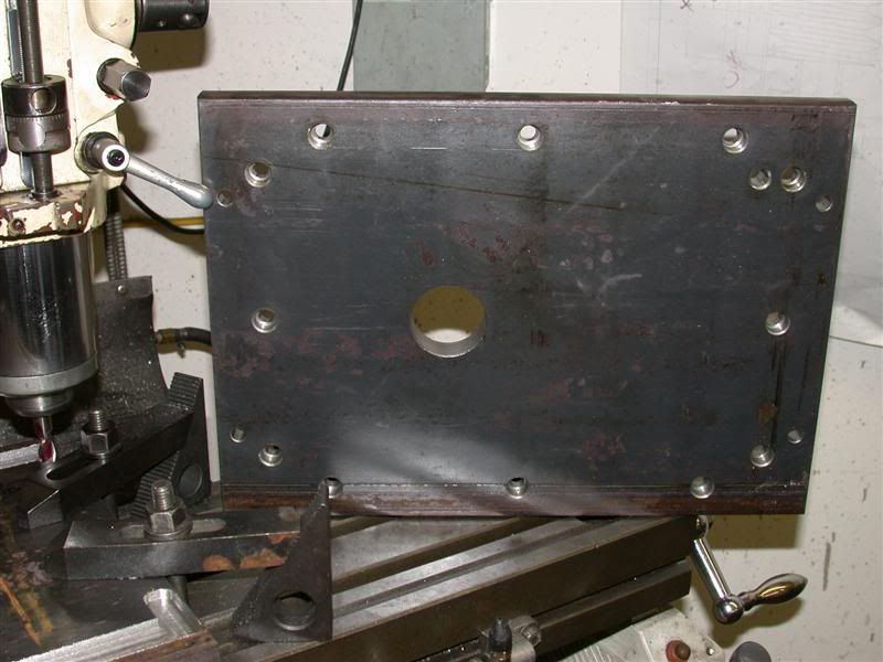
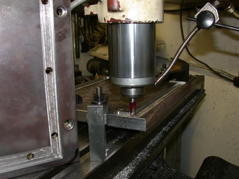
There is a lot of prep work to make sure the plates are square and parallel for when I do my hole bores. I'll know they will line up and not be cockeyed to each other causing binding or something.

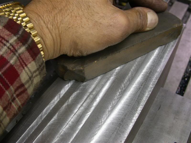
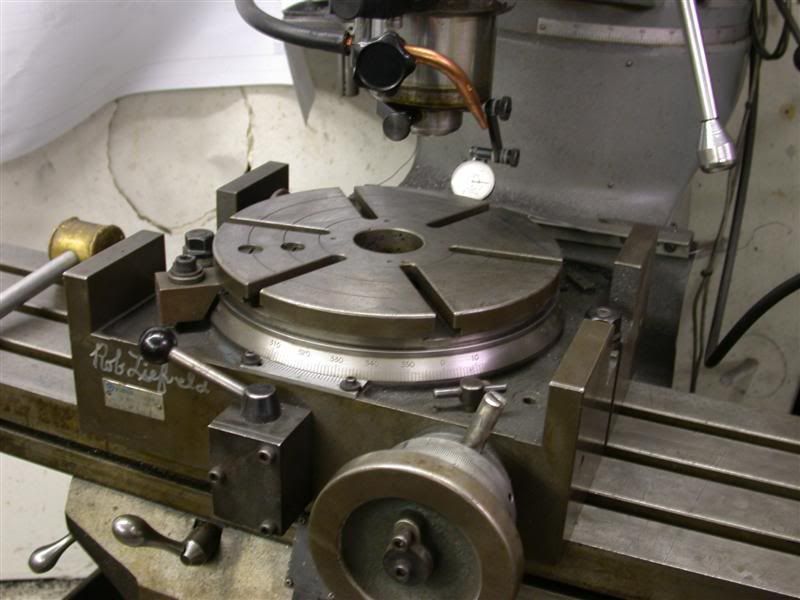
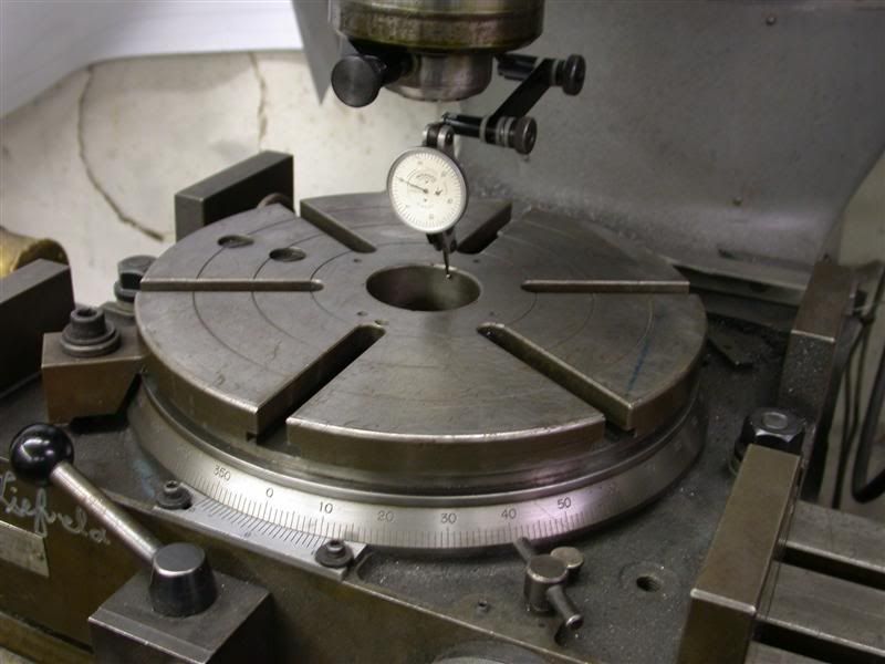
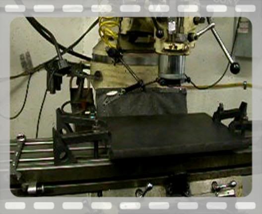
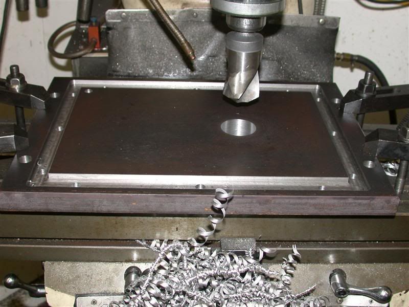
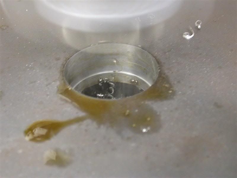
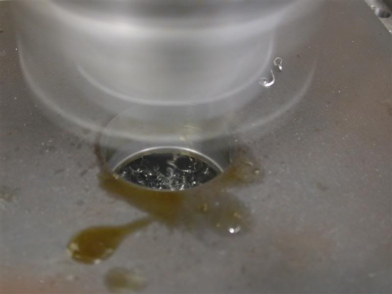
Here's a short video of one pass. Sorry it's not that great but I had to dodge hot chips while filming. It only shows the last strip being cut left on the longer plates though.


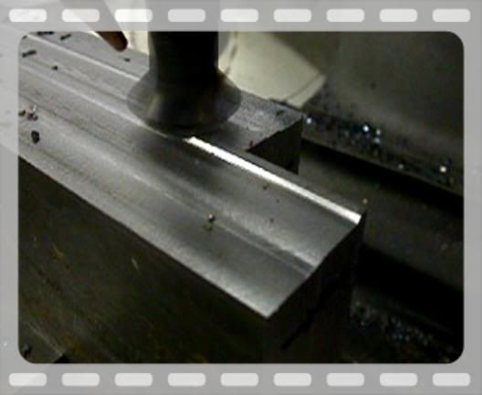
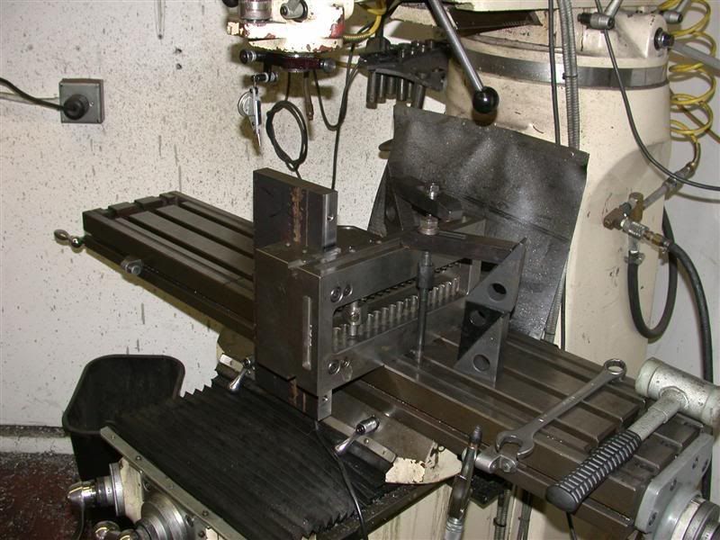
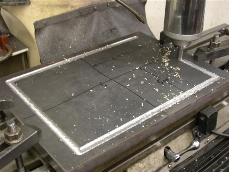
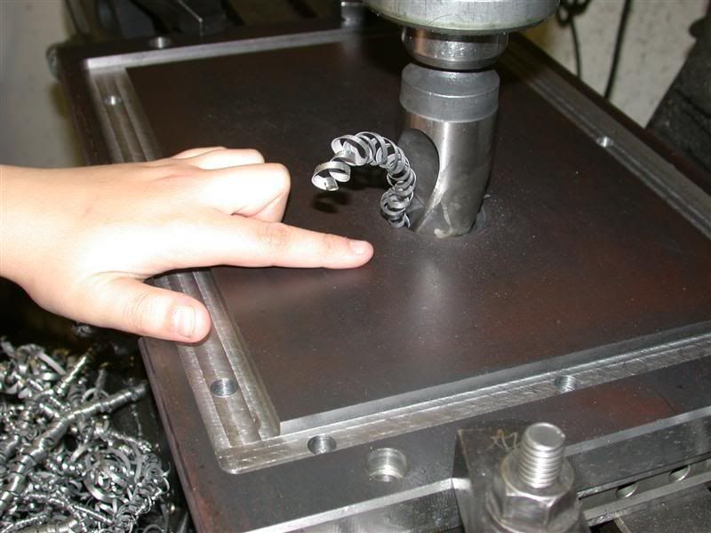
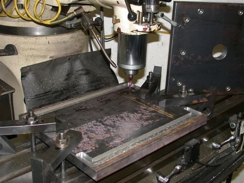
I was machining .080" a pass at 20" a minute (approx) with air cooling the inserted carbide mill cutter. I machined all the plates together because they all had to end up the same size.

Rob-
 
   / 360* Rotating Back Blade Project
  • Thread Starter
#22  
Back to the work now, I took the entire vise off the mill with the plates still clamped up in it. Then checked it on the surface plate to see if the plates had moved. I used and InterRapid indicator to check for level.


Then had to stone all the cuts and edges to remove any burrs.


Rob-
 
   / 360* Rotating Back Blade Project
  • Thread Starter
#23  
I wanted to surface grind this dimension for a couple reasons. I needed the plates to be exactly the same height to avoid leaks, but more important, when I do the boring I can measure for exact locations accurately.

So first I had to dress the surface grinding wheel with a diamond dresser. (Also a home made one). Then I placed the vise with the plates still clamped in it all on the magnetic chuck.


And started surface grinding the plates while in the vise. I kept them in the vise so the first edge I grind will be square to the flat part of the plates. My vise jaw is square so I know it will come out good.


Rob-
 
   / 360* Rotating Back Blade Project
  • Thread Starter
#24  
Once I got the top side ground, I took the entire set up out of the grinder and clamped the plates together before taking them out of the vise. My vise alone weighs 65 pounds so with the 4 side plates in it the whole thing has to weigh about 140 pounds.
Anyway, I took the clamped up plates out of the vise and put them back on the grinder resting on the newly ground surface. And ground the other side down to size. Surface grinding you can only take about a half thousands to a thousands at a time, so you have to mill within about .006" of the finished size.
Here are the plates resting on the squared up ground side by themselves.


This is a good picture of my home made vise next to the plates. It is a little shorter than the Kurt Angle Lock vises some of you have, but with much greater standard clamping ability due to it's design. It's about 14" long vs 17" but has 6-1/2" wide jaws instead of 6" on the Kurt vise. Also, it is square all the way around so I can hold stuff sideways or even upside down if I want. On the Kurt vises, you can remove the jaws from inside and bolt one to the back and the other one on the front (by the handle and hold stuff on top of the vise. But then clamping force and getting stuff dead square becomes an issue. I've had the mill throw lots of work pieces ... rip it right out of all kinds of vises. :(


Rob-
 
   / 360* Rotating Back Blade Project
  • Thread Starter
#25  
OK, so here they are ready for tomorrow's machining. They have all been checked for size and squareness and came out pretty good. They are +.0005" over size ( a half thousands) but that may be because they are a little warm. :D


Soon,I will start drilling and boring the holes in the side and top plates. I'll do all the mill work first and then the lathe work last, to fit to my bores. There is still a lot of work left to do. But I am having a really good time as this is my favorite thing to do.
Rob-
 
   / 360* Rotating Back Blade Project
  • Thread Starter
#26  
OK, my report for tonight starts with tearing my vise down from the older mill and putting on the new mill. Then Put the rotary table on the old mill. Indicate the back edge to make it straight with the x table.


Then indicate the center of it to line the quill center to it.


This all in preparation for tomorrows machining where I will rough out the large Ø4-1/4" bores for the retaining bushings. In the mean time, I set the Chevalier mill up with the vise and an angle plate as a stop for all the drilling and tapping of the 3/8-16 holes. Each set up is time consuming because they have to be bolted down to the tables and indicated in perfectly so all my machining repeats.


Rob-
 
   / 360* Rotating Back Blade Project
  • Thread Starter
#27  
Altogether, there will be 98 holes to drill & tap, counter sink & counter bore, not including any extra lift holes or handle holes. The tapped holes will need to be drilled at least 1-1/4" deep each so I can have enough thread tapped in it. That's a lot of steel to drill out.

This is what I do for every single hole.
First is to center drill each one to guarantee location and so that the drill doesn't walk off center.


Next is to drill with the tap size drill. Notice that the center drilled hole has a deep enough chamfer to leave a lead in. Always try to use the correct size center drill so you get this lead in and it then remains a chamfer even after it is tapped. Then there is less stoning (deburring) to do after and the threads are not mushed over.


Then you can tap the holes. These holes were drilled 1-1/4" deep and tapped 1" deep.


Rob-
 
   / 360* Rotating Back Blade Project
  • Thread Starter
#28  
Following that, there are those holes that need to counter bored and counter sunk so the SHCS sit completely in them. I have a set of counter bores for every cap screw up to 5/8-11. The hole for these is 1/32" over the nominal screw diameter.


Here you can see them finished and chamfered, with a cap screw submerged in the right one. Larry's project needs to look really good so every single hole will be like these.


You may have seen some "X's" on the steel. I mark all the plates the way they have been milled and ground so if there is any mis-alignment or un-square surface, they will still match up as a set. On my molds, each mold plate is stamped permanently for this reason.

Rob-
 
   / 360* Rotating Back Blade Project
  • Thread Starter
#29  
One problem is how to drill and tap the long pieces that don't fit under the quill. They are too long for the drill chuck with drill in it to hold in a vise. So what I do for these is take my precision vise and turn it sideways. I position it so the workpiece hangs over the edge of the table, missing the locks and stops. Then indicate it all in square and clamp the workpiece in it.


When pieces are REALLY long, I've even rotated my column so the quill is not over the table, but off to one side. Then I clamp the workpiece either directly to the side of the table on in my vise like above. I have the bottom sitting on dowel pins on the floor so I can move the tables. ???

Here's another view where I've just finished tipping the long ends and they are done. My vise jaws are .001" narrower than the vise body so I can still move the jaw when it's clamped like this. ;)


Rob-
 
   / 360* Rotating Back Blade Project
  • Thread Starter
#30  
Here is the box minus the top and bottom plates. It is very square and should be easy to assemble. The 2 end plates are now 100% done. Larry will have to sand the HRS finish off the sides if he wants, but I would just paint it. The other side plates will go back into the milling machine for additional drilled and tap holes for the hydraulic motor and they will get rotary tabled and bored out for the bushings, thrust bearings and oil seals yet. Then there are the top and bottoms that have all kinds of machining on them too, before I get to the internal components.


I'll see how far I get because tomorrow is one of my golf days. I also had to lengthen my 2 iron a little for added distance and will need to re-grip it in the morning. (I hope Larry doesn't read that part.) So maybe this weekend with a couple extra days 'till completion? This shouldn't take longer than a week of work (not including design time), but I don't work on it steady so it will take me about 2 weeks to do 1 weeks work. :)
Rob-
 
   / 360* Rotating Back Blade Project
  • Thread Starter
#31  
I had a few minutes to burn before my tee time and decided to set up the bottom plate for the pocket milling on it. I positioned it so that I would have enough travel in all directions and then indicated it in square and found center. Here is a video of how to indicate and find center on a large piece.


After indicating it square and parallel to the table axis, use your indicator and pick up the high point at each edge. Use the quill to lower the indicator and move it from side to side and you will see where the high point is as the needle goes to a spot in one direction and then reverses. That spot is the high point so move the dial to zero. Then swing over to the other side and see what that reads. Then split the difference and move the dial again to zero and check both sides until they read the same. Then you are on the dead middle of the piece in that direction. Set your DRO to zero. Then do it for the other direction too and you will be on center. Round pieces are easy as you can sweep around the diameter.

You can also use a depth mic and measure to a pin in the quill and do the same thing. I like using the test indicator for better accuracy.

Here's the first part of the pocket I am milling where the box will sit in and be "trapped" by the steel plate.


Pocket milling has to be exact because if you miss a dimension, you could cut a groove to the outside. So you have to pay attention on this type of machining. You also need to measure frequently because of cutter flex. Your finish pass should be the same depth of cut as the last pass used to measure. This assures you the end mill will cut the same amount off as you have measured. Otherwise it might vary and you'll cut more or less than anticipated.


Rob-
 
   / 360* Rotating Back Blade Project
  • Thread Starter
#32  
Here you can see I had to mill the ends square. I set my 1-2-3 blocks up with a test indicator in a surface gage right on the mill table to check while machining.


Rob-
 
   / 360* Rotating Back Blade Project
  • Thread Starter
#33  
Oooh wee,
I got lucky ... the side plates fit the pockets perfectly and the pocket is the right size. I gage blocked the box dimensions and did the same for the pocket dimensions.

In milling the pockets, I not only had to fit the width of each plate respectively, but just as important, hold the outside and inside dimensions when the sides are bolted together. I ended up clearing the inside pocket by.001" per side but held the outside dimension right on the number. That will keep the box from flexing outwards 100% and the screws now only hold it together in the middle.

Here is a picture of the plates sitting in their pockets. Ends are .750" thick and sides are 1.000" thick.


I have lots more to do to this plate. Drill and counter bore for all the SHCS (socket head cap screws) and bores for the worm gear. I still have to establish the bottom of the pocket too, you might have seen the red Dykem on the bottom? When pocket milling, except when roughing, you don't want to cut the sides and the bottom at the same time or the cutter may suck down and there goes your depth. So I rough the pocket out near depth, lower the table so my cutter is off the bottom by about .020' and then start cutting the sides. Then I go back and cut the bottom finished and stay away .001" from the sides. Lots of steps to take and stuff to remember if you want your work to turn out good.

I also have to radius the end plates to match the radius of the pocket. All this was a huge step because I now have numbers to reference to when I do the top plate. I say reference, because I will still individually check each size to be certain it fits and works rather than take it for granted.
Rob-
 
   / 360* Rotating Back Blade Project
  • Thread Starter
#34  
After seeing what Rob's been up to, I figured, I too better get with the program. Today I hooked up the Back Blade to my tractor for the very first time. I painted the drive coupler and attached it with the 1/2" shear bolt. Then I made up the hoses with quick connects that will attach to the hydraulic motor to drive the worm. The control valve is all hooked up and ready to go.

In addition to the 90* worm Gear Drive that Rob is so painstakingly machining for me, I want to use a hydraulic cylinder to adjust the swing offset. I have this cylinder lying around so I set it in place to see if it will work.


Here I am holding the Hydraulic lines and analyzing the situation.


I’ll have to wait till the mounting bracket for the gear box is installed before I can mount the swing offset cylinder. It will be an integral part of the gear box mount.

Larry
 
   / 360* Rotating Back Blade Project
  • Thread Starter
#35  
Hahaha, don't hurt yourself Larry. Looks like real back breaking work there. ;D ;D ;D But your blade sure looks nice. I was just picturing the gear box and hydraulic cylinder on top of that spline shaft. It is going to look really cool for sure.

While Larry is slaving away in New Mexico, his Californian big brother has been busy too. As I said earlier, the pocket milling is strenuous and nerve racking since a mistake or a misread would send a steel wall out of bounds. The top plate should go a little faster with experience I gained from doing this one.
The mill cuts came out really nice and clean.


With that out of the way, the rest of the machining was drilling and counter boring for the SHCS. I sure hope they all line up? ???
I'll still have to flip the plate over for the counter bores on the other side though....and I still have to chamfer all the holes. They are still sharp edged now. That one hole in the corner inside the box will be Larry's drain hole. I will put a giant lead in on that one and tap the other side 1/4"NPT.


I also rough drilled out the hole for the Ø2" hollow spline shaft.
I say rough drilled because I will bore it to size to be sure it is on location. Many times a big drill like this will walk off several thousands so boring it after will put it back on location.
Here is Wesley showing the size of this drill.


Today is his birthday. He turned 11. Loretta and I took him to Sportsmart after his Karate lesson to get him a gym bag to punch and kick the **** out of. He wanted one for practice training.

So that's all I got done today.
Tomorrow after golf, (if I feel like it ;)), I'll bore that hole and finish up the bottom plate. Then start on the top plate. After they are both to the same state, they will go in the rotary table to open up the counter bores for the collars and oil seals.


BTW, did you notice I was able to mill and drill every single hole without taking my set-up down or moving any clamps? Also managed to miss drilling the parallels that hold the plate above the table. I hope Larry figures out that hose routing soon. :D

Rob-
 
   / 360* Rotating Back Blade Project
  • Thread Starter
#36  
I talked to the boss (Larry) today and he told me to get it in gear.
He told me he wanted it by April and I said "You mean this year?" LOL ... So I better get on with it. Really, Larry has been very (overly) thankful and shown his appreciation very much.

Tonight I got the hole bored out for where the hollow spline shaft will stick through the bottom plate. I'm taking it to Ø2.008" at 550rpm using the boring feed on the milling machine. The feed indicator has 1-½, 3 and 6 for feed rate and is tied in with the RPM. I never did know what that meant. The 1-½ is the slowest and 6 the fastest feed. For holes around this size I usually rough at 6 taking .030" per side and finish at 3 taking .010" per side. Otherwise the cutter on the boring bar wears out. I guess large diameter holes would need the 1-½ rate? Who cares...

Here are some boring pictures.
Start boring...


Halfway through...


And near the bottom...


Side Note:
When boring I also always use cutting oil or STAT oil which is a compound oil that seems to work better for real high speed, high rpm cutting. We used to use it on the Deckel GK21 Pantograph machines when running about 20,000 rpm with little tiny cutters. With the advent of CNC's, I don't know anybody that knows how to run them anymore. (Or even what they are?) I used regular dark cutting oil on these holes.

Rob-
 
   / 360* Rotating Back Blade Project
  • Thread Starter
#37  
Here is the bottom plate all finished except the counter bores that will hold the thrust bearings, collars and oil seals. Oh, and will also machine a big radius on every corner yet, so Larry doesn't bust his shins on it.


I have also set up and roughed what I can on the top plate. I am using the numbers from the bottom plate as a guide to get me close to the finished dimensions. I roughed these out with a 4 flute solid carbide endmill but will finish with a 2 flute hi speed endmill for better finish. I will be taking less of a pass and the chips clear better/faster with the 2 flute.


Unfortunately, the top plate is shorter than the bottom plate so I can't mill the entire pocket in one set-up. I've set the plate up so I can mill the long pockets and part of the ends and I can still drill all the holes. But I will have to reset the plate 90° and pick up centers again to finish the end slots. Not only that, but I'll have to do that 2 times because the end slots are too far apart for the "y" travel on my mill to do both in the same set-up.. Bummer.

Getting pretty close to seeing the light at the end of the tunnel ... and it ain't a train!
Rob-
 
   / 360* Rotating Back Blade Project
  • Thread Starter
#38  
I am completely dumbfounded with the amount of work Rob has accomplished in such a short period of time. I think I got a pretty good deal for 9 minuets of my time to “repair” Rob’s tractor wouldn’t you say?

So now were up to date on this project – So what do you think so far?


Larry
 
   / 360* Rotating Back Blade Project #39  
WOW Larry,
What a documentation you have started! I can't wait to see How it ends up. Sure hope it works just as you planned. I'll be the first to say you definitely got your 9 minutes worth!:) Of course you forgot to mention you spent all weekend re-wiring my tractor and installed a complete new automotive fuse box in it and fixed a whole bunch of troublesome electrical connections on top of that. You are too gracious to even mention that.
This is a fun project.
 
   / 360* Rotating Back Blade Project
  • Thread Starter
#40  
3RRL said:
WOW Larry,
What a documentation you have started! I can't wait to see How it ends up. Sure hope it works just as you planned.
Yea me too, I'm counting on you to make that happen for me! Not that it matters or anything - It took me nearly 8 hours to compile all your documentaion into Word so that I could post it. I've got 22 pages of text, pictures and HTML code :eek:

3RRL said:
I'll be the first to say you definitely got your 9 minutes worth!:) Of course you forgot to mention you spent all weekend re-wiring my tractor and installed a complete new automotive fuse box in it and fixed a whole bunch of troublesome electrical connections on top of that. You are too gracious to even mention that.
This is a fun project.

Thanks for the generous compliments :D The way you make your machining look easy for you is what electronics and wiring is for me. I'm sure glad this is a fun project for you. I was getting a little worried there.

I guess I bored everyone ? no replies yet :confused:

Larry
 

Tractor & Equipment Auctions

2361 (A60432)
2361 (A60432)
2020 DRAGON ESP 150BBL ALUMINUM (A58214)
2020 DRAGON ESP...
PALLET OF (20) BOXES OF CARPET SQUARES (A60432)
PALLET OF (20)...
2017 Toro Sand Pro 5040 Bunker Rake (A59228)
2017 Toro Sand Pro...
2016 VOLVO SD75B SMOOTH DRUM ROLLER (A60429)
2016 VOLVO SD75B...
2019 CATERPILLAR  XQ35 GENERATOR (A58214)
2019 CATERPILLAR...
 
Top