360* Rotating Back Blade Project

   / 360* Rotating Back Blade Project
  • Thread Starter
#21  
There is a lot of prep work to make sure the plates are square and parallel for when I do my hole bores. I'll know they will line up and not be cockeyed to each other causing binding or something.

Here's a short video of one pass. Sorry it's not that great but I had to dodge hot chips while filming. It only shows the last strip being cut left on the longer plates though.


I was machining .080" a pass at 20" a minute (approx) with air cooling the inserted carbide mill cutter. I machined all the plates together because they all had to end up the same size.

Rob-
 
   / 360* Rotating Back Blade Project
  • Thread Starter
#22  
Back to the work now, I took the entire vise off the mill with the plates still clamped up in it. Then checked it on the surface plate to see if the plates had moved. I used and InterRapid indicator to check for level.


Then had to stone all the cuts and edges to remove any burrs.


Rob-
 
   / 360* Rotating Back Blade Project
  • Thread Starter
#23  
I wanted to surface grind this dimension for a couple reasons. I needed the plates to be exactly the same height to avoid leaks, but more important, when I do the boring I can measure for exact locations accurately.

So first I had to dress the surface grinding wheel with a diamond dresser. (Also a home made one). Then I placed the vise with the plates still clamped in it all on the magnetic chuck.


And started surface grinding the plates while in the vise. I kept them in the vise so the first edge I grind will be square to the flat part of the plates. My vise jaw is square so I know it will come out good.


Rob-
 
   / 360* Rotating Back Blade Project
  • Thread Starter
#24  
Once I got the top side ground, I took the entire set up out of the grinder and clamped the plates together before taking them out of the vise. My vise alone weighs 65 pounds so with the 4 side plates in it the whole thing has to weigh about 140 pounds.
Anyway, I took the clamped up plates out of the vise and put them back on the grinder resting on the newly ground surface. And ground the other side down to size. Surface grinding you can only take about a half thousands to a thousands at a time, so you have to mill within about .006" of the finished size.
Here are the plates resting on the squared up ground side by themselves.


This is a good picture of my home made vise next to the plates. It is a little shorter than the Kurt Angle Lock vises some of you have, but with much greater standard clamping ability due to it's design. It's about 14" long vs 17" but has 6-1/2" wide jaws instead of 6" on the Kurt vise. Also, it is square all the way around so I can hold stuff sideways or even upside down if I want. On the Kurt vises, you can remove the jaws from inside and bolt one to the back and the other one on the front (by the handle and hold stuff on top of the vise. But then clamping force and getting stuff dead square becomes an issue. I've had the mill throw lots of work pieces ... rip it right out of all kinds of vises. :(


Rob-
 
   / 360* Rotating Back Blade Project
  • Thread Starter
#25  
OK, so here they are ready for tomorrow's machining. They have all been checked for size and squareness and came out pretty good. They are +.0005" over size ( a half thousands) but that may be because they are a little warm. :D


Soon,I will start drilling and boring the holes in the side and top plates. I'll do all the mill work first and then the lathe work last, to fit to my bores. There is still a lot of work left to do. But I am having a really good time as this is my favorite thing to do.
Rob-
 
   / 360* Rotating Back Blade Project
  • Thread Starter
#26  
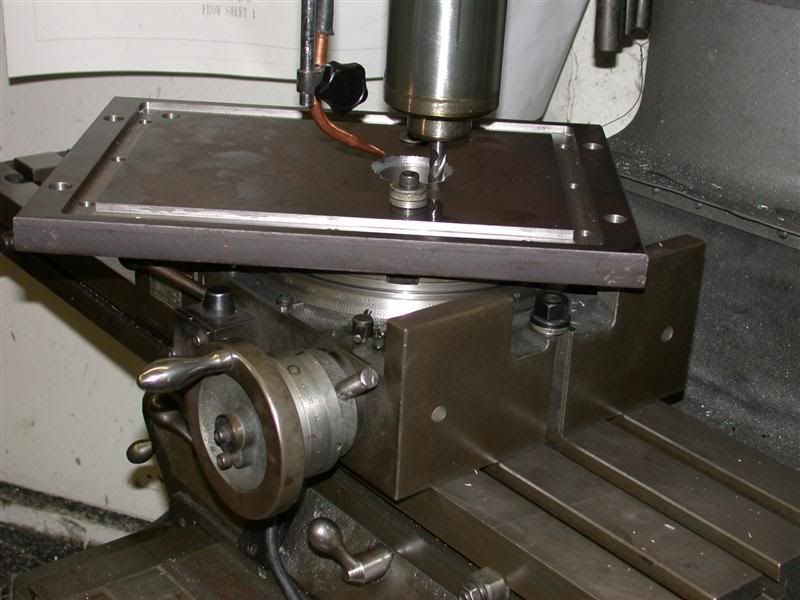
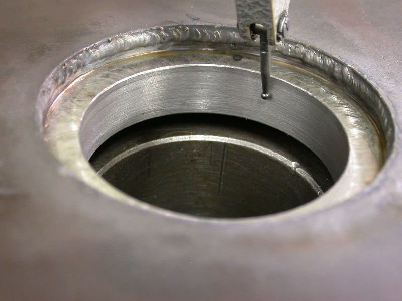
OK, my report for tonight starts with tearing my vise down from the older mill and putting on the new mill. Then Put the rotary table on the old mill. Indicate the back edge to make it straight with the x table.


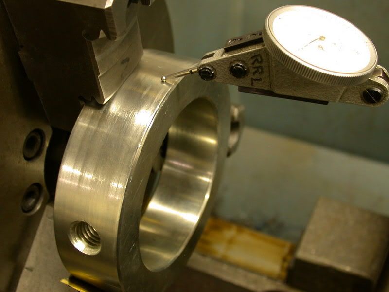
Then indicate the center of it to line the quill center to it.


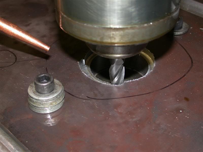
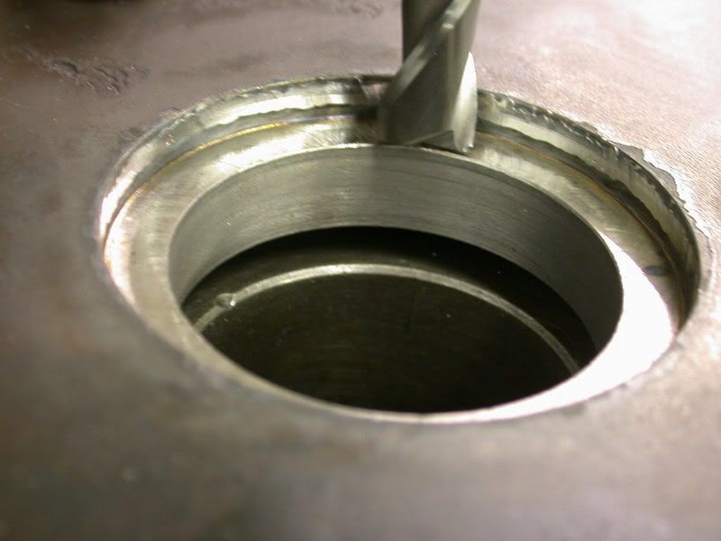
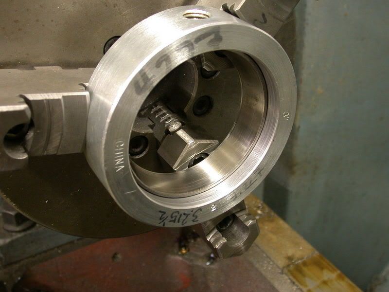
This all in preparation for tomorrows machining where I will rough out the large Ø4-1/4" bores for the retaining bushings. In the mean time, I set the Chevalier mill up with the vise and an angle plate as a stop for all the drilling and tapping of the 3/8-16 holes. Each set up is time consuming because they have to be bolted down to the tables and indicated in perfectly so all my machining repeats.


Rob-
 
   / 360* Rotating Back Blade Project
  • Thread Starter
#27  
Altogether, there will be 98 holes to drill & tap, counter sink & counter bore, not including any extra lift holes or handle holes. The tapped holes will need to be drilled at least 1-1/4" deep each so I can have enough thread tapped in it. That's a lot of steel to drill out.

This is what I do for every single hole.
First is to center drill each one to guarantee location and so that the drill doesn't walk off center.


Next is to drill with the tap size drill. Notice that the center drilled hole has a deep enough chamfer to leave a lead in. Always try to use the correct size center drill so you get this lead in and it then remains a chamfer even after it is tapped. Then there is less stoning (deburring) to do after and the threads are not mushed over.


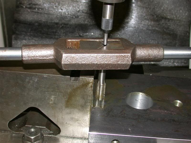
Then you can tap the holes. These holes were drilled 1-1/4" deep and tapped 1" deep.


Rob-
 
   / 360* Rotating Back Blade Project
  • Thread Starter
#28  
Following that, there are those holes that need to counter bored and counter sunk so the SHCS sit completely in them. I have a set of counter bores for every cap screw up to 5/8-11. The hole for these is 1/32" over the nominal screw diameter.


Here you can see them finished and chamfered, with a cap screw submerged in the right one. Larry's project needs to look really good so every single hole will be like these.


You may have seen some "X's" on the steel. I mark all the plates the way they have been milled and ground so if there is any mis-alignment or un-square surface, they will still match up as a set. On my molds, each mold plate is stamped permanently for this reason.

Rob-
 
   / 360* Rotating Back Blade Project
  • Thread Starter
#29  
One problem is how to drill and tap the long pieces that don't fit under the quill. They are too long for the drill chuck with drill in it to hold in a vise. So what I do for these is take my precision vise and turn it sideways. I position it so the workpiece hangs over the edge of the table, missing the locks and stops. Then indicate it all in square and clamp the workpiece in it.


When pieces are REALLY long, I've even rotated my column so the quill is not over the table, but off to one side. Then I clamp the workpiece either directly to the side of the table on in my vise like above. I have the bottom sitting on dowel pins on the floor so I can move the tables. ???

Here's another view where I've just finished tipping the long ends and they are done. My vise jaws are .001" narrower than the vise body so I can still move the jaw when it's clamped like this. ;)


Rob-
 
   / 360* Rotating Back Blade Project
  • Thread Starter
#30  
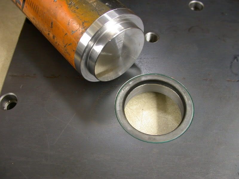
Here is the box minus the top and bottom plates. It is very square and should be easy to assemble. The 2 end plates are now 100% done. Larry will have to sand the HRS finish off the sides if he wants, but I would just paint it. The other side plates will go back into the milling machine for additional drilled and tap holes for the hydraulic motor and they will get rotary tabled and bored out for the bushings, thrust bearings and oil seals yet. Then there are the top and bottoms that have all kinds of machining on them too, before I get to the internal components.


I'll see how far I get because tomorrow is one of my golf days. I also had to lengthen my 2 iron a little for added distance and will need to re-grip it in the morning. (I hope Larry doesn't read that part.) So maybe this weekend with a couple extra days 'till completion? This shouldn't take longer than a week of work (not including design time), but I don't work on it steady so it will take me about 2 weeks to do 1 weeks work. :)
Rob-
 

Tractor & Equipment Auctions

2011 Nissan Titan SV 4x4 Crew Cab Pickup Truck (A50323)
2011 Nissan Titan...
Diesel Fuel Tank with Pump (A50860)
Diesel Fuel Tank...
2007 GMC Sierra 2500 HD Flatbed Pickup Truck (A50860)
2007 GMC Sierra...
2018 HINO 268 26FT BOX TRUCK (A51222)
2018 HINO 268 26FT...
2006 GMC 4500 Bucket Truck with Altec AT200 - 34FT Working Height (A51039)
2006 GMC 4500...
2013 CAT 950K WHEEL LOADER (A50854)
2013 CAT 950K...
 
Top