2manyrocks
Super Member
- Joined
- Jul 28, 2007
- Messages
- 9,543
Pictures????????
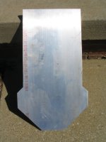
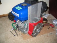
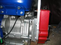
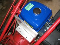
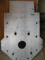
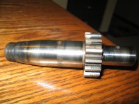
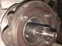
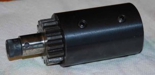
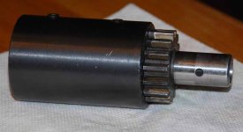
Although my project is a long way from being done, here are a few pictures to give everyone an idea of what I am up to. The first is of the 1/2" aluminum plate after I cut it with a circular saw (it needed a little clean-up with a jig saw). The second is with the adapter unit bolted to the engine. The third is a side view showing two small rectangular plates serving as spacers behind the large 1/2" plate. I needed a 1 1/4" spacer behind the large plate but didn't have one so I used a 1/2" plate along with a 3/4" plate. The last photo is the engine bolted loosely to the tractor. Notice the small aluminum plate covering the crankcase (studs are poking thru). I deliberately made the 1/2" plate bolted to the crankcase tall until I figure out how to attach the handlebars. It will eventually get cut down to the needed height. By the way, the total width of the plates and crankcase is 4". This will leave about 1 1/2" of the gear shaft available to be covered by the the keyed sleeve. Hope this helps describe what I'm doing.
Excellent Bruce,,, simple and not a bunch of spendy machine work by the looks of things. Sooooo,, have you got a running machine yet??
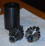
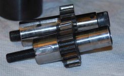
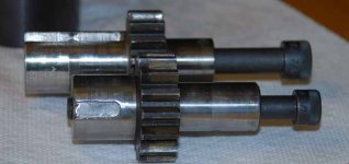
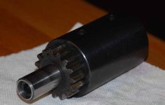
So are you saying that you use the two piece adaptor to mount the engine to the Gravely transmission housing, and the input shaft to transfer power from the engine to the transmission? That's what is involved here in repowering a Gravely with a new engine?
Yes a Kohler adapter and 2 spacers
What about repowering with those 11-13 HP "Chondas" from HF? The 6.5 engines made by Lifan appear to have a following on some websites, but I wondered if the 11-13 clones did as well as the 6.5 clones?