You are using an out of date browser. It may not display this or other websites correctly.
You should upgrade or use an alternative browser.
You should upgrade or use an alternative browser.
Geothermal Heat Pump Project
- Thread starter techman
- Start date
- Views: 21264
More options
Who Replied?
/ Geothermal Heat Pump Project
#21
Chapter 7
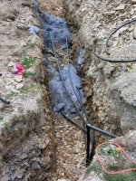
As the loop work progressed, I had the misfortune that a heat wave in the 90's was persisting for the entire time. No rain, but hot and tiring conditions. Laying the bottom pipe and covering it with screenings was relatively easy work. Carrying and maneuvering the coils, especially around the piles of dirt, was sometimes a challenge, but manageable. The greatest challenge was when the spoil pile transitioned from the inside of the loop to the outside. At that transition I had to carry the 2/3 complete coils over the trench, using a 2x6 I had as a plank over the hole. There was not much clearance with the spoil piles, and it was a bit tricky at times.
The next job was to put approx. 2' of backfill in the trench. Using the FEL I tried but was never able to get a nice even fill across the trench. Great effort with shovel, rake, hoe and pick was needed to get the layer somewhat level, so I could lay the tubes and cover them with screenings. Where possible I used the BH on the tractor and did a sweep with the side of the bucket to try to level out the dirt. It helped, but with all of the shale, way too much manual labor was still needed. This was the absolutely most difficult portion of the job. After the job was done, I spoke with another installer who said he had gone to digging with a 4' bucket and laying all 4 tubes on the bottom of the trench. A real labor saver which I will do on my next job this summer.
After both layers of tubes were in, and the header area was still fully exposed, I did a pressure test. I kluged together the fittings to get an air fitting and gauge in the line. I used air and pumped up to 100 PSI and held it for 1 hour, the reduced it 50 PSI and let it sit for 18 hours. I did not want to leave the high pressure in long term due to concern that daytime heating might push the pressure higher, and I did not fully trust my test jig. The 50 held solid, concluding my test. The loop will run at 20-30 PSI, so the test was 2-3 times higher.
Some recommend testing with water, which can show up leaks more readily due to the minimal compressibility, but water takes a lot more work and can get messy later on when working on the piping. It is not easy to get the water out again. Using air you need to let the temperature stabilize in the air so that temp variations do not effect the results.
After the testing I finished the backfilling. The fill was over 600 tons (calculated) and took several solid days of tractoring. I was stopped twice by hose breaks on the tractor. Several years old and there was days of high load/high shock work so I was not entirely surprised. Trips to the local Parker hose store got me back in operation each time. In the end I had to have about 60-70 tons of dirt hauled away. This was a combination of the fact that all of the dirt never seems to go back in a hole (especially with shale) and all of the screening tonnage I put in.
Time for more pix.
Continued on Chapter 8
paul

Chapter 8
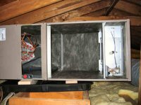
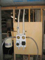
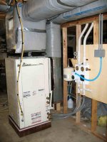
The inside work was now starting. First was to get the circ panel in. To connect the loop to the circ panel, I transitioned to PVC with standard glue joints. Temps and conditions are fine for PVC, and if there is a joint problem, it is readily accessible. I added a small expansion tank (recommended to me) to keep the loop pressure steadier. The manufacturers do not recommend a tank, and the loop pressure varies from about 30 PSI to 80 PSI seasonally. Using the small tank I have had a 3-4 PSI variation. A potable water tank should be used. They have the fluid in contact only with the bladder, and not the steel surface (furnace tanks sometimes have the air in the bladder and water against steel). Using this style minimizes the chance of any corrosion in the loop.
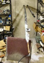
Another decision was to use bent joints in the PVC rather than fittings. This was done to reduce pressure drops in the loop, to maximize flow rate. Bending was done with a heat gun and layout table. You need to be careful to maintain diameter and avoid wall thinning when bending PVC. Experience at it is the best tool.
The panel has the pump and a blanking cover for a second pump, used in the 2 pump models. The brass disks are the 3-way valves to select closed, flushing or running positions. The side fittings are for flushing and the bottom fittings go to the units..
Continued on Chapter 9
paul
The inside work was now starting. First was to get the circ panel in. To connect the loop to the circ panel, I transitioned to PVC with standard glue joints. Temps and conditions are fine for PVC, and if there is a joint problem, it is readily accessible. I added a small expansion tank (recommended to me) to keep the loop pressure steadier. The manufacturers do not recommend a tank, and the loop pressure varies from about 30 PSI to 80 PSI seasonally. Using the small tank I have had a 3-4 PSI variation. A potable water tank should be used. They have the fluid in contact only with the bladder, and not the steel surface (furnace tanks sometimes have the air in the bladder and water against steel). Using this style minimizes the chance of any corrosion in the loop.
Another decision was to use bent joints in the PVC rather than fittings. This was done to reduce pressure drops in the loop, to maximize flow rate. Bending was done with a heat gun and layout table. You need to be careful to maintain diameter and avoid wall thinning when bending PVC. Experience at it is the best tool.
The panel has the pump and a blanking cover for a second pump, used in the 2 pump models. The brass disks are the 3-way valves to select closed, flushing or running positions. The side fittings are for flushing and the bottom fittings go to the units..
Continued on Chapter 9
paul
Attachments
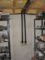
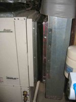
View of the piping transition to PVC. Note the bent tube runs. The lines are fully insulated now. By early January the temperature of the pipes reached the dew point in the basement and started raining. 3/4" rubber insulation was applied to all of the pipe runs to stop the condensation.
Paul
Paul
Attachments
kenmac
Super Member
- Joined
- Feb 13, 2005
- Messages
- 9,903
- Location
- The Heart of Dixie
- Tractor
- McCormick CX105 Kubota MX 5100 HST,
Is that slate rock that you had to dig in ?I hope it all works out well for you as that's alot of work . Even at cost , that system cost alot of $. Thanks for sharing this project with us.
Scozz
Silver Member
Paul thanks for taking the time to share this with us. I've been in HVAC for 25 years but haven't touched geo thermal once. This is very interesting to me. BTW, is there no concern that the shale may cut a line after years of ground movement? Keep up the great work...Scozz
Chapter 9
With the loop plumbing done, the next job was to install the 1st floor unit. Having removed the old equipment, installing the new geo unit was relatively straight forward. The tin knocker made adapters for the plenum and return ducts, and some trimming and bending later the connections were ready. The unit was places on a few course of bricks to get it off the floor. On top of them a layer of foam for some sound and vibration insulation followed by a layer of rubber vibration pads from the supply house. I was told that the unit is VERY quiet, but that it should be mounted on a vibration pad and that any base support material should be a soild layer. Apparently if you mount it with say a perimeter of bricks or blocks, the base plate can flex with compressor vibration and amplify the noise.
Electrical hookup was straight forward. It was now time to fill and flush the loop. Since I did not have a flush cart (although I could have borrowed one, but schedule was a potential issue), I used an alternate (but recommended) method. To achieve the required 30 GPM and 30 PSI min flushing requirements, I used a 1 HP pool pump. A 35 gallon high side plastic storage tote served as the tank.
First the loop is filled and flushed. The valving on the circulator panel was set to that configuration and the loop filled from a hose. I started the high flow flushing with the pool pump and quickly realized how much air was in the loop. A couple of hours and a lot more water later the loop was finally fully filled, with minimal air left. I flushed for about 4 more hours. During this flush, the flow was reversed in the loop every 30 minutes or so, and between that time the return flow was shut off rapidly (using an in line 1" ball valve), allowing the loop to pressurize to 30-50 PSI pump pressure, then the valve is quickly opened to help remove small lodged pocket of air and minimize dissolved gasses. By having the return flow in the tank below the water surface, it was easy to see any air bubbles in the flow as I flushed.
Satisfied that the loop was sufficiently flushed, I next added the antifreeze. This was done by running the flushing as before, but initially dumping the return flow outside (drain) until there was just enough level in the tank to keep the pump supplied. Then the 5 gallon buckets of methanol mix (30%) are poured into the tank and into the loop. During this time the return is still drained outside until the last couple of buckets of antifreeze provided a reasonable level in the flush tank. Then the return was restored back into the flush tank. The result is the antifreeze being charged into the loop and in the end the flushing is continued with the antifreeze. Only a premixed methanol solution should be used indoors so that it is below the concentration where it is flammable, and ventilation of the work area is a must.
In the end the loop holds about 100 gallons of fluid. The methanol is selected to give the desired freeze temperature for the system. The loop was flushed for another 4-6 hours to eliminate any remaining air that may have been introduced with the methanol, and also to help mix the methanol throughout the loop.
Next was to fill the heat pump water circuit and piping. The circulator panel valves were changed to connect the flush ports to the geo unit. The flush pump was used to fill the unit from the antifreeze mix that was in the flush tank. Again a few hours of flushing to remove air, and the valving was changed again to connect the loop, geo unit and flush ports all together. Several more hours of flushing of the complete system and checking for any remaining air bubbles the system was finally ready. The last step was to pressurize the loop. This can be done with a hose from the water supply, or as I did it with the flush pump. I set the air charge in the expansion tank and opened the valve to connect it to the loop. I started the flush pump and used the ball valves at the flush pump/return to trap about 20 PSI in the loop. The valves on the circulator panel were then set to the normal run configuration. The system was ready to run.
All in all the fill and flush took 2 full days. With some experience, it can be done in one day if everything is in place and ready.
More on Chapter 10
paul
Attachments
Chapter 10
I fired up the 1st floor unit and voila...heat came out. After starting the unit, I was somewhat shocked at how loud the unit was. I felt betrayed by what I was told. It seemed like having the old outside heatpump in my basement. I was ready to complain to the supplier, but being a weekend, he was closed. Getting things wrapped up, I decided for now I had to live with it, so I put all of the cover panels back on. The heat started running again and much to my surprise, all I could hear was the blower/airflow noises. Amazingly the cover panels (they had insulation on the inside) completely eliminated the compressor noise. I am sure that the panels also help stiffen the frame which adds to the noise reduction.
Initial observations were that the exiting air was warmer than I ever had on my older air source units. The other surprise is that you feel usable heat out of the unit within about 10 seconds of starting. The elimination of the long freon lines gets the system operating at capacity is a very short time.
During that startup day, I was doing some rerouting of wires, etc, and I did not realize it but I knocked the wire off of the relay for the circulator. The unit started up and a few minutes later it faulted out on a low loop temp shutdown. Restarting it would result in a shut down in 30 seconds (time delay on faults). I found the problem, but could not get it to keep running. Soon I realized that running without the loop circulator caused the antifreeze mix to freeze to a slush consistency throughout the exchanger in the unit. I let it sit for a few hours and was finally able to get it to run again. I put it into A/C mode to warm the heat exchanger and pump the slush out of the unit.
More on Chapter 11
paul
Chapter 11
The next task was the 2nd floor attic unit. I removed the old equipment. The attic air handler needed to be disassembled to make handling and clearance easier. I had hoped to reuse the existing freon lines to the attic, but earlier on realized that the specs for the geo unit called for larger lines for the higher rated efficiency. I unfortunately had no easy straight shot through any walls between the attic and basement. Even though the air handler and compressor units were almost directly above/below each other, the freon line would route to the outside wall where the existing lines ran.
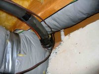
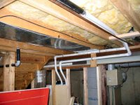
I attached a 1/2" hemp rope to the old lines and pulled the lines out of the wall. I had put them in when the house was built, so I knew that it was a straight shot with generous clearance holes through the 2x4 plates. The lines came out very easily. I attached the new lines to the rope and started to feed them through. It ended up taking a couple of hours to finally get then through the passage. No matter how straight you think you have the copper lines, when you have a confined space to uncoil and feed, it is not straight enough. Finally after multiple tries, I got it from attic to basement. The major issue became the opening in the basement. The line needed to negotiate a double "S" path to clear the sill plate, foundation wall, existing (and unmovable) ductwork and an I beam (see attached pix). I ended up feeding 6-12", going to the basement and bending and shaping the lines, then back to the attic to push a bit more. Unfortunately I did not have a helper that day, which would have helped tremendously. It was about a total of 12 hours to get the freon line run and in place.
Being November, I expected nice coolweather for the attic work, but with my luck another heat wave. Mid 80's and sunny mahe it mid to upper 90's in the attic. No choice to wait since I knew if it turned cold, it would be cold enough to require heat. I got the new handler up in pieces and reassembled in the attic. As I had stated, I was replacing a York AH with a new York or the same model line. I quickly discovered that the duct interfaces on both ends were completely changed. Another trip to the tin knocker produced a new return duct adapter and a new supply plenum.
Getting it all mounted and connected was relatively straight forward. Wiring, brazing the lines, leak testing, and condensate line connections were all the same as a conventional system. The only small difference was the recommendations by the manufacturer that the liguid line (small one) should be insulated. Normally only the vapor line is insulated, but due to the efficiency and operating conditions, the added insulation improves the overall performance.
Except for the heat and cramped working conditions, all went as expected.
More on Chapter 12
paul
The next task was the 2nd floor attic unit. I removed the old equipment. The attic air handler needed to be disassembled to make handling and clearance easier. I had hoped to reuse the existing freon lines to the attic, but earlier on realized that the specs for the geo unit called for larger lines for the higher rated efficiency. I unfortunately had no easy straight shot through any walls between the attic and basement. Even though the air handler and compressor units were almost directly above/below each other, the freon line would route to the outside wall where the existing lines ran.
I attached a 1/2" hemp rope to the old lines and pulled the lines out of the wall. I had put them in when the house was built, so I knew that it was a straight shot with generous clearance holes through the 2x4 plates. The lines came out very easily. I attached the new lines to the rope and started to feed them through. It ended up taking a couple of hours to finally get then through the passage. No matter how straight you think you have the copper lines, when you have a confined space to uncoil and feed, it is not straight enough. Finally after multiple tries, I got it from attic to basement. The major issue became the opening in the basement. The line needed to negotiate a double "S" path to clear the sill plate, foundation wall, existing (and unmovable) ductwork and an I beam (see attached pix). I ended up feeding 6-12", going to the basement and bending and shaping the lines, then back to the attic to push a bit more. Unfortunately I did not have a helper that day, which would have helped tremendously. It was about a total of 12 hours to get the freon line run and in place.
Being November, I expected nice coolweather for the attic work, but with my luck another heat wave. Mid 80's and sunny mahe it mid to upper 90's in the attic. No choice to wait since I knew if it turned cold, it would be cold enough to require heat. I got the new handler up in pieces and reassembled in the attic. As I had stated, I was replacing a York AH with a new York or the same model line. I quickly discovered that the duct interfaces on both ends were completely changed. Another trip to the tin knocker produced a new return duct adapter and a new supply plenum.
Getting it all mounted and connected was relatively straight forward. Wiring, brazing the lines, leak testing, and condensate line connections were all the same as a conventional system. The only small difference was the recommendations by the manufacturer that the liguid line (small one) should be insulated. Normally only the vapor line is insulated, but due to the efficiency and operating conditions, the added insulation improves the overall performance.
Except for the heat and cramped working conditions, all went as expected.
More on Chapter 12
paul