Glow Plug Timer control units

   / Glow Plug Timer control units #11  
Althought I am clueless about electronics, I have great pleasure to follow your thread.
You have just given out a great idea to get some electronics repaird at a fraction of the new part price: Go to a TV/Computer repair shop to get it fixed! Thank you.
In this regard you help other electronics clueless members!:thumbsup::)


I tried to do that with a circuit board for a geothermal heating unit. I forget the name of the component, but I believe it limits the starting current. Anyway, there was no way I could find to buy a new replacement component without going through Warefurnace. Let's hope that there are replacement parts available in the open market - I didn't have any such luck at the time. I guess you win some and lose some.
 
   / Glow Plug Timer control units
  • Thread Starter
#12  
Hey guys, thanx so much for your interest and comments. Wasn't sure how this would be received, but I knew there were plenty of fix-it-yerself folks on here. DFB, yeah, kinda figured that there were other/different configuratons of glow plug timers out there. Hope this thread helps others diagnosing all those other types.

The saga continues:

Examining and probing my original NGK S81NF-1 LampTimer showed that the suspect capacitor C2 is okay.
The problem turned out to be the latch section transistors Q2 & Q3 failed. Will try fixing later.

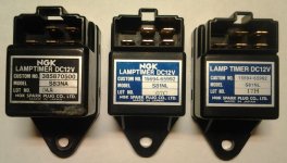
So, I decided to use the new NGK S81NL-1 for my tractor.
But, I wanted to extend the 'on' time a little, and get rid of that flickering problem.

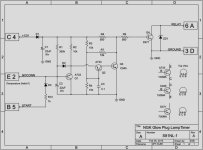
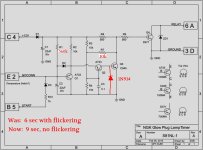
Replacing the timer resistor R1, from a 390k to a 560k, extended the 'on' time to 9 seconds.
Replacing latch resistor R7, from an 18k to a 10k, got rid of that unstable flickering.

During probing, I noticed that the voltage of the single connection between latch transistors Q2's collector and Q3's base would drop to around -3v to -4v during the initial delayed 'on' time. I don't like this. Having the base of an NPN transistor going to a lower voltage than its emitter isn't good. So, I decided to protect Q3 by adding a 1N914 diode between that line and ground. It still goes negative, by a small fraction of a volt, but stays well within NPN transistor safety margins.

I'm familiar with emitter-follower and darlington configurations, but this is the first time I've seen this collector-base setup.

Maybe this is why these things fail so much.

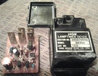
This is what the MODIFIED NGK S81NL-1 LampTimer PCB looks like:
(old/replaced resistors at bottom of picture)
MOD-NGK-S81NL-1-pcb.jpg

This is the MODIFIED NGK S81NL-1 LampTimer circuit schematic:
(Annotations in red)
MOD-NGK-S81NL-1-sch.jpg
 
   / Glow Plug Timer control units #13  
I like your MODIFIED thinking - that's why my FIL's faulty glow plug controller (timer plus an engine temp cutout circuit) is going to be modified by replacing it with a momentary-contact switch on the dash. Might cost $10 including a couple of connectors and a bit of scrap wire.

I used to like tinkering in the circuitry but it has gotten to where so much of it is SMD that its impossible to troubleshoot or repair, and even when there's discreet components, suitably-spec'ed replacements are hard to find. Nice that Digi-Key has a lot of no-minimum order items and reasonable shipping prices.

- Jay
 
   / Glow Plug Timer control units
  • Thread Starter
#14  
JRobyn, ditto on the modern electronics. That's why I was pleasantly surprised to find a vintage '80s circuit in there. Found that this NGK design originated in the 80's, when things like this used simple Resistor/Capacitor timing circuits, like windshield wiper timers, headlight/domelight delays, flashing LEDs, and such. The transistors in my broken unit are very common, no special features, and I think I can fix it using some typical grab-bag stuff in my shop...
 
   / Glow Plug Timer control units
  • Thread Starter
#15  
Something I should've mentioned in the other posts:

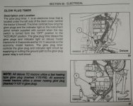
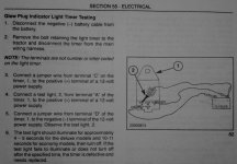
Some sections of the tractor manual use letters to identify the timer's pin-outs, other sections use numbers, and some of the timers have numbers to identify the pins. To avoid confusion, I've used both letters and numbers to identify the pins. For example, the +12v power pin may be referred to as 'C' or '4', so I've labelled it as 'C4'.


So, I've fixed my original NGK S81NF-1 LampTimer.
The suspected latch section transistors Q2 & Q3 were okay afterall.

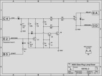
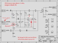
The problem was: Diode D3 was shorted.
This allowed the the timing charge to drain, through resistors R10, R11, and diode D4, into Q4's base.
The timer wouldn't complete its cycle, leaving the glow plugs turned on.
My guess is that the current inrush from the start override pin B5, into cap C2, damages the diode.
Also found, like with the other timer, that there was a flickering problem, and Q3's base would drop to around -3v to -4v.

So, here's an addendum to the LampTimer bench test:
(Specific to the NGK S81NF-1 with starter override only)

1. Connect a voltmeter's negative lead to the ground pin, 3D.
2. Connect the voltmeter's positive lead to the NoConnect (Temp sensor) pin, E2.
3. During test, the voltage should slowly rise to about 4.5-5.0 volts, then the test lamp goes out.
4. If the voltage never rises above about 3 volts, suspect diode D3.

Now for the mods:

1. Replaced latch resistor R7, from an 18k to a 10k, to stop the unstable flickering.
2. Added a 1N914 protection diode between Q3's base and ground.

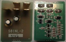
This is what the REPAIRED/MODIFIED NGK S81NF-1 LampTimer PCB looks like:
FIX-NGK-S81NF-1-pcb.jpg

This is the REPAIRED/MODIFIED NGK S81NF-1 LampTimer circuit schematic:
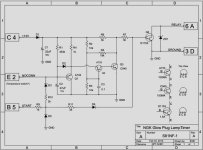
(Annotations in red)
FIX-NGK-S81NF-1-sch.jpg
 
   / Glow Plug Timer control units #16  
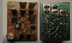
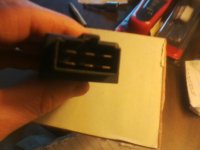
I have a small Volvo excavator with Mitsubishi S3L2 engine and I have a issue with glow relay timer. Timer works ok when I power it up, but problem is that timer doesn't shutdown glowing att all (glow time should be ~6,2 seconds according workshop manual). Timer is looking like this:


I didn't found any reasonable price direct replacement sparepart from Europe, does anyone know can I replace my timer with this: http://www.ebay.com/itm/NGK-Lamptim...632780957?&clk_rvr_id=892938497681&rmvSB=true . One thing I noticed that S81-NL has 5 pins (extra pin is for engine temperature sensor?) and my old S85-NC has only 4 pins.

Of course if someone has some ideas how to fix that old one? I already tried to solder all again, but with no success.

Thanks
 
   / Glow Plug Timer control units #17  
If my experience (Mitsubishi 3cyl in Cub Cadet 7260) holds true, even if you find a substitute, it will be pricey. As in $75USD+. It was a really simple and cheap alternative to wire up a momentary contact pushbutton. The dash even had a pre-punched hole for a switch.

If you do, check the schematic to be sure to wire your pushbutton in the circuit for the existing glowplug relay coil, and not in place of the actual relay contacts. The coil is low amperage, the contacts are HIGH amperage and would require a much larger and more expensive switch.

- Jay

p.s. - You probably already noticed that it looks like the larger blue resistor shows some signs of heat, so it might be worth pulling and checking/replacing that. And interesting that your old housing says it's a S85-NC but the actual circuit board says it's a S81-NJ. I'm pretty sure you are correct about the 5th terminal being engine temp sensor connection. That's what's on the one for the Mitsubishi/Cub and what SG51 noted in previous posts.

p.p.s. - and in re-reading SG51's excellent posts, I note that his failure mode (staying on) is the same as yours, so quite likely that your latch diode D3 is knackered.
 
Last edited:
   / Glow Plug Timer control units
  • Thread Starter
#18  
Hi dippa and JRobyn. Been awhile since I've been on here. This site's interlinked advertizing does things that crash my tablet, so I can't get on here much. Experienced 4 crashes already just reading this thread.

There's some signs of overheating on that PC board, so a component or several have failed.
For this particular issue, I'd need to have the old timer unit in-hand, the schematic for the Volvo/Mitsubishi glow plug circuit, and the new timer unit in-hand.

From what I was able to determine from my New Holland issue, is that the main connector pinouts seem to be common, but the differences are in the features (temp switch) and timing value. I was able to repair mine, but had to replace a few components. The fact that it's similar to the Kubota timer is interesting.

The timer you're considering may easily interchange, but I'd recommend a close examination and comparison with the original unit first. Be prepared for unusual variations.

I guess what I'm trying to say here is: "I haven't a clue."

If any other members have particular knowledge of dippa's timer issue, please chime in...
 
   / Glow Plug Timer control units
  • Thread Starter
#19  
I just re-read this thread and most of the imbedded pictures don't come up.
Were they deleted?
 
   / Glow Plug Timer control units #20  
All the pics are still there for me (using Chrome). That sux having crashes. Sounds like maybe you need to install "Ad Blocker Plus"?

- Jay
 

Tractor & Equipment Auctions

8Yd Dumpster (A44571)
2016 Ford Fusion S Sedan (A44572)
2016 Ford Fusion S...
Heavy-Duty 4-Wheel Rolling Warehouse Cart  74in x 32in (A44789)
Heavy-Duty 4-Wheel...
International 656 (A44501)
International 656...
ATTENTION! PLEASE READ (A44502)
ATTENTION! PLEASE...
6Yd Dumpster (A44571)
 
Top