There are two ways that interference gets onto wiring: Electrostatic (or E-Field) and Magnetic. For the purpose of this discussion, we'll include Radio Frequency (or RF) as part of electrostatic.
Electrostatic shielding can be done by any piece of metal. So you can have the braid on a coax, the foil shield on a cable, or have the wire in a metal pipe. Typically the metal is connected to ground. The electrostatic/RF field can not penetrate the metal very well, so the wires inside of the shield are protected. Different types of shielding and grounding systems have different amounts of percentage of shielding you get. But unless you are close to a high power radio transmitting site things like coax and foil shielding will work just fine.
The way to shield against magnetic fields is with a twist of the wire. How often the wire is twisted depends on how high of a frequency you have on the wire (or in geek speak "what is the bandwidth of the signal"). If anyone can recall back to the days of open telephone wires (or look at pictures), every few poles there is what was called a transposition bracket which swapped the sides of the wire as they were on the poles. For telephone bandwidth, that was good enough. As you go from cat3 to cat5, the big change is the amount of twisting and the consistency of the twist. That's why cat5 can handle higher bandwidths (now measured in bits per second instead of some frequency) than cat3.
The predominate mode of interference from AC power is magnetic. So the twists in the cat5 cable go a long way to protect it from interference. Coax is harder to shield, and if you have baseband video on the coax you can often see problems with shielding as the "hum bars" that will be slightly but annoyingly visible. When there is RF on the coax (like your satellite dish, cable, or TV antenna) the interference from the AC does not have much energy at the frequencies that are on the coax, and things work out fairly well. FWIW, I always use quad shielded coax because it's easier to be cautious than lucky.
One more interesting thing about fields: The energy falls off as the inverse of the square of the distance. Oh geez, don't yell "No, Not MATH:shocked:" it's easy to explain this :laughing:! If you double the distance between two wires, the field strength is 1/4 what it was. If you move the wires to 4 times further away, the field strength is 1/16th what it was. So take the "new distance" between two wires. Square that distance, and then take the reciprocal (i.e. 1/<the number>). A little bit of distance makes a big difference in the levels of interference.
Practically speaking: Imagine you had AC and CAT5 wires that were laying on each other, which might put the wires 1/4" apart. Now move the wires so they are 2 inches apart. This is 8 times the distance you originally had, so the field is 1/64th as strong. Pretty good deal for such a small change in spacing.
So when running wires, you want them to cross at right angles as much as you can. You do not want to parallel them if you can help it. And you want to get as much distance as you can between them. More than 4 inches of distance and you'll never see the difference. Going to great lengths to get more than 4 inches of separation is not worth it.
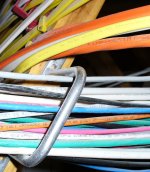
Drill and use separate holes for AC and for low voltage. The inspectors will want to see this. Use the wire supports to keep the wires apart.
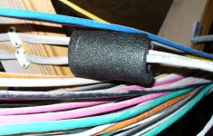
Here are some pictures. My helpers when I wired my place got the low voltage on both sides of the AC in a spot. So I took a piece of pipe insulation and went from 1/4" apart to about .75" apart or 1/10th the coupling. And that is over a small area.
You can put the pipe insulation on either wire (AC or LV- you can see examples of both in the pictures), but if it's more that a short piece of insulation I'd go for the Low Voltage and not the AC wiring.
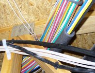
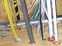
Finally, you can see where I came through a smoke block and had separate holes for LV. Note also that I kept some of my coax away from everything (by about 4 inches). In fact, I tended to group my wiring into these groups:
CAT5, speaker wires, wires that ran relays, coax, and AC. All those types had some separation between them. If you look in the upper left of the picture, you'll se a bunch of gray wires. These go to coils of relays for turning on lights. I also had a run of two coaxes from the attic to the basement. These went to my off-air antennas. I had those 1' away from everything up until the last 12' before they came into the room with all the connections. I also ran an 18 gauge wire for powering amplifiers for these antennas so the signal levels would be stronger both for interference and signal loss reasons.
One trend that has made the interference problem better is that all things electronic have to pass radio emissions testing. So things like dimmers tend to not produce the "hash noise" they used to when they first came out. There is also less motor noise. This is nice because hash noise _is_ RF and might require that all this cat5 cable be shielded. But with reduced RF from the AC lines, it boils down to a magnetic shielding problem that is solved via the twist in the wires.
Also keep in mind that virtually every protocol a computer runs when doing communications via Ethernet on CAT5 cable has error detection and a means of correction. So a little once in a blue moon hiccup from something big turning on or a lightning storm isn't a problem. Relative to the speed of light, a blue moon could be every couple minutes or so.
So to the OP, parallel for a short distance is OK, try to get 2 to 4 inches between the wires. The cat5 will be just fine for your network stuff.
Clear as mud?
Pete