1963 Case 530CK Backhoe/Loader

   / 1963 Case 530CK Backhoe/Loader #61  
Been lurking here and following this with great interest. It's September 15 now, no new posts for 2 months-please don't keep us in suspense!
 
   / 1963 Case 530CK Backhoe/Loader
  • Thread Starter
#62  
Been lurking here and following this with great interest. It's September 15 now, no new posts for 2 months-please don't keep us in suspense!

Well MEMEMEME, I'm sorry that I've not stayed current concerning my Case 530 project. I got busy with other things and neglected my hoe project. I've been painting the house (three coats walls and soffits and fascias) and a myriad of summer labors and as a consequence kind of let you folks down with up to date posts as a result. Rest assured that I have plenty more pictures and details to come. I've just about finished the tractor part (and of course will still post the remainder of that), but still have the tower, boom, stick, and bucket and all of the attendant hydraulics, pins, bushings, hoses to restore, I won't let you down, I promise..........:thumbsup:
 
   / 1963 Case 530CK Backhoe/Loader
  • Thread Starter
#64  
Ok, here is my finish presentation on the front axle group:

IMG_1682_rs.jpg
You are looking at the left side front spindle and axle as I assemble all of the seals, cups, cones, and shims for a dry fit. I found the one of the previous owners did not understand the inter working relationship between the vertical spindles tapered splines and the steering arms matching splines. The adjustment of the two can be simple if you understand that the two must mate with no play in the splines but just enough preload on the thrust bearing sandwiched between two washers that have tapered recesses machined in them. When I originally acquired the loader/hoe, I found the front spindles were so loose that I could not run the tractor in high gear. They had welded the spindle nut to the washers, then to the arm thinking that they had taken the play out of the group. And then I think when they realized that the front end was still wobbly and loose after they had welded everything together, they just left the mess! So, I used a 1/16"x3" pneumatic cutting wheel to cut the welds without destroying any of the parts, and proceeded to separate and clean up the nut and spindle arm. Now I needed to consider how I could improve the fit-up between the male and female splines. I found that to tighten up the fit you must remove shims that would have been between the upper axle housing and the steering arm so that the tapered splines can engage more, but none were there to remove. And because of the bad fit, the actual spline had been wallowed out and not the crisp fit that one would expect from a properly assembled axle. At this point, the only way to bring them into further contact was to machine the two tapered washers that sandwich the thrust bearing, thus allowing the vertical spindle to penetrate deeper into the steering arm. It took several attempts on the lathe, taking off .005 at a time before a good fit was achieved. I had to do this on both sides.

IMG_1692_rs.jpg
Here is the assembly after final fit-up with wheel spindle and hub greased and adjusted. By the way, after cleaning all of the old grease and dirt out of hub, I chucked them up in my lathe and really cleaned up the mating surfaces. If you notice in this picture you will see a pressed sheet metal seal cuff that screws to the backside of the hub, I spent more time straightening those than all of the time that I spent on the hubs. The wheel bearings were in great shape and were adjusted well, so I only had to clean re-grease and re-install everything. Only had to replace the seal, but that's normal anyway. I installed new power steering cylinders. It turned out that the threading on the shaft and knuckle were poor and when I tried to screw them together they started to strip out. So I was lucky to back them out and re-thread them. I think some of this stuff is of poor quality and is coming out of China.

IMG_1690_rs.jpg
This of course is the other side and if you look closely you can see some of the stripped threads on the knuckle shaft. I was lucky and able to save the threads thus the parts and complete the connection.

IMG_1693_rs.jpg
Had to do a little more work on this sides hub, but with satisfactory results!

IMG_1698_rs.jpg
Both sides finished, adjusted and ready for paint.

IMG_1699_rs.jpg
In this view you can see the two washers and thrust bearing that I explained earlier that I reduced them so that the spindle could engage the arm more. I have yet to install the new tie rod.

IMG_1717_rs.jpg
Tie rod on, everything adjusted and grease with a fresh coat of paint. Boy, it sure is good to have the front end done, there has really been a lot of effort expended on this part of the loader but I know it will pay off in the long run! Thanks for the interest guys, it makes it worth the effort to post.

IMG_1723_rs.jpg
 
   / 1963 Case 530CK Backhoe/Loader
  • Thread Starter
#65  
This post shows the sheet metal dash, fuel tank, hood, and grill being prepped and some of the body work part 1.

IMG_1358_rs.jpg
Here's how it looked after tank removal and dash................what a mess!

IMG_1366_rs.jpg
Another view of steering wheel and dash and wiring harness before prep and paint.
IMG_1447_rs.jpg

IMG_1483_rs.jpg
After removing as many dents and as I could reasonably take care of and removing all paint, here is the hood and tank. I had to have a radiator guy repair the fuel tank, it was leaking quite badly at the return from the injection pump and the water collector cup. The guy cut off the petcock flush with the bottom of the water collector cup soldered a penny over the hole at the bottom of the cup closed because he couldn't get the shut off petcock to come out of the threads so it was ruined. But, he did a real sanitary job, and anyway here in Nevada I don't think a guy has to worry too much about moisture in the air or fuel. Since it is kind of hard to find a replacement tank and my tank didn't have any rust inside I felt it was the cheapest way to go.

IMG_1875_rs.jpg
Here is the anvil that I fabricated to hammer the dents out of the radius of the hood. I mounted it in one of my jack stands and it worked out really well. It was a piece of 2 1/2"x7" round 1018 welded to 1 1/2"x 3" rectangle tube stock.

IMG_1686_rs.jpg
This on shows the power steering hard lines and the dash and tank mount painted and installed ready for the parts.

IMG_1814_rs.jpg
Front grill and structural front mounted on the front axle housing.

IMG_1863_rs.jpg
Fit up and check all of the mounting places before painting.

IMG_1864_rs.jpg
Left side in place and if you look closely you can see the new lower sheet metal ears that I had to fabricate then weld on the hood. They are actually the hold downs for hood to fuel tank. They interlock with the seam where the factory fabricated the tank. They tend to be a part that fatigues from diesel engine vibration and at least on mine were completely missing. The hood was just sort of rattling around on the top of the fuel tank. I just took some 16 gauge sheet metal and made a cardboard pattern, then cut the sheet metal with my electric shears. After cutting out the pieces then bending the radius in the bottom part to match the radius in the tank, I then drilled a whole to match the threaded nut in the tank, then welded the ears to the inside of the hood and blended the weld with my grinder to get a smooth finish ready for paint.

IMG_1867_rs.jpg
Right side fit up.

IMG_1870_rs.jpg
Just a closer look at how it fits. Next installment I'll show you the finished part and of course the installation.
 
   / 1963 Case 530CK Backhoe/Loader #66  
This is definitely a labor of love. By the time you are done it won't be a 1963 but a 2016 Case 530K Backhoe/tractor.
You are doing a superb restoration job. I enjoy following your progress.
PAGUY
 
   / 1963 Case 530CK Backhoe/Loader #67  
This is definitely a labor of love. By the time you are done it won't be a 1963 but a 2016 Case 530K Backhoe/tractor.
You are doing a superb restoration job. I enjoy following your progress.
PAGUY
 
   / 1963 Case 530CK Backhoe/Loader
  • Thread Starter
#68  
This is definitely a labor of love. By the time you are done it won't be a 1963 but a 2016 Case 530K Backhoe/tractor.
You are doing a superb restoration job. I enjoy following your progress.
PAGUY

Thanks PAGUY,
It has been a labor of love. I can tell you had I not been retired I could never have thrown the time or effort at this project. I'm sure I'd have just settled with getting the main stuff fixed and leaks stopped and then started using it. Also, I had never seen anyone do a total restore on an old loader/backhoe, I've seen many regular tractor and badly damaged new hoes restored, but never an old one. So, that really interested me. I have really learned a lot doing this and this job has helped me tune up my machinist skills. I've welded ever since high school and for the most part am real comfortable welding, but I had to get pretty creative in some of the machining that I did.
 
   / 1963 Case 530CK Backhoe/Loader
  • Thread Starter
#69  
Here is the 2nd part to my sheet metal post. It was a real pleasure to be painting and installing all of this stuff, rather than cleaning, welding, grinding and bending the necessary parts. Hope you enjoy.

IMG_1915_rs.jpg
I was finally getting some primer on the sheet metal. I won't show pictures of all the parts being primed, but included this one to show you how nice it was to finally have the part be all the same color. The dash panel had broken in two at that narrow strip that you can see in the lower left hand side. That strip of sheet metal was only about a 1/4" wide. I think the constant flexing at that weak point fatigued and finally broke. I welded another strip the same width on the back side to reinforce it and then welded the holes that had been drilled in the face for the sheet metal screws that attached the plate containing (3) 2" diameter gauges. Then ground the welds down to match the surface of the dash.

IMG_1943_rs.jpg
Same dash just has a fresh coat of paint and ready to install.

IMG_1941_rs.jpg
Thought you would enjoy seeing the backside of that same dash with paint and kind of gives a perspective of the spot welded reinforcements on the interior. In the background you can see the finished loader arms with the steering wheel removing puller that I fabricated hanging as a counter balance. It offsets the weight that the steel plates that are welded on the other side of the arms. That steel is the bracket that the leveling cylinder attaches to, which make the arms hang crooked and just makes the job of painting easier if its level.

IMG_1884_rs.jpg
Most of the dents came out of the hood but a person can only spend so much time on removing dents.

IMG_1883_rs.jpg
I was pleased with how the fuel tank turned out. I had to straighten out the three attachment metal points on the tank and rethread the nuts and re-do the threaded studs on the bottom of the tank but I think that's normal for a restore.

IMG_1967_rs.jpg
This one shows the dash and tank now mounted and wiring harness threaded and attached where it's supposed to be. Before I set the gauge cluster, I had to rebuild it. I found it on eBay and it was pretty rough. I disassembled it then carefully cleaned all of the surfaces and made sure all of hands on the gauges inside worked freely then cleaned and polished the glass and sealed it with a new rubber ring gasket that I fabricated out of some glazing bead. I reset the hour meter to 0, then re-assembled everything and it seems to all work now. You'll also notice a new steering wheel, which I didn't tighten the nut on yet until I've started the engine, pumped though power steering fluid and find the power steering motor is not leaking, I didn't wan to fully engage the splines, then have to use my wheel puller and possibly mar the surface of the wheel if I somehow I had a leak and need to pull it back off to fix.

IMG_1972_rs.jpg
I included this one to show how the wiring harness feeds into the dash area. I still had quite a few wires to hook to their proper places. The Company that I bought this harness from is located in New York and they just did a perfect job with good instruction too! I also installed the newer style diesel shut off handle, it's the red pull handle on the far left, I thought it looked kind of cool.

IMG_1980_rsz_rs.jpg
The reason that I included this picture is it shows the sheet metal lower dash shrouds that I fabricated out of 16 gauge sheet metal. Of course I made a cardboard template then transferred the image to the sheet metal. I added two tabs one on the top and one on the side, then bent the sheet metal on my brake. After punching two holes in each tab lined up behind the holes in the dash; makes for a cleaner looking finish to the dash and I think more protection for the wires. I reversed the template for the other side, then painted and mounted them both with sheet metal screws.

IMG_1975_rs.jpg
Finally got the hood, tank, and dash mounted. That's a long decal and a guy has to be real careful installing it. I almost had a crash with this one but learned from my mistake and it made it easier doing the other side!

IMG_1976_rs.jpg
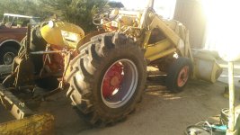
Got the radiator installed and started to line up and fit the hard lines to the hydraulic pump. This was also the point where I was finally installing most of the hard lines and forward wiring harness. If you look in about the center of the picture you can also see the voltage regulator and wires. We're getting closer.

IMG_1981_rs.jpg
Another perspective that shows most stuff bolted on and decals finished.

IMG_1984_rs.jpg
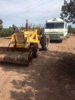
Final shot of the tractor with one of the structural arms on just before I was going to install the loader arms and shaft. The bolts connecting this arm to the front end, axle, and docking bar should not be tightened, because when mounting the other side and loader arms there needs to be some play between all of the parts or you can't push through the 1 1/2" shaft that connects both sides. Once you have all of the holes aligned, the shaft greased, the whole thing goes together pretty well and can now be tightened to specifications. Anyway, I was happy with how the sheet metal turned out!
 
   / 1963 Case 530CK Backhoe/Loader #70  
Sure does look good TY for all your posts good intensive for others to see what can be done.
 
   / 1963 Case 530CK Backhoe/Loader #71  
Incredible job so far! You have a great deal of talent in all areas of the restoration and I've really enjoyed following this thread.
 
   / 1963 Case 530CK Backhoe/Loader
  • Thread Starter
#72  
This part of the project took a lot of time because of the condition and size of the loader bucket. There was so much straightening and heating and welding and grinding to do, and the size of it required some creative thinking. The doggone thing can hurt you fast if you don't sling it right or haven't thought out your maneuver before trying to pick it. Some of the following pictures show the various stages as the project progressed.

IMG_2002_rs.jpg
After doing all of the straightening and installing (3) new hooks on the mold board of the bucket, I hung some spare chain on the hook and took a picture.

IMG_2006_rs.jpg
This is one of the hooks, when I bought them, they come as a set, I prepped the surface and welded them on. I use the eye mainly in the center to attach a pick, but thought that having these additional hooks would still be handy for a load that may need the spread, like a long pole or tree trunk or such.

IMG_2013_rs.jpg
This one shows the finished paint removal and some of the bushings that I replaced in the bucket bosses. Also welded up some of the cracks and areas along the bucket side cutters. In the center of the bucket you can see a couple of fish plates that I bent and covered a rip-out from too much pressure being applied from prying out dirt or rocks with the bucket. On the reverse side of the bucket you will notice a rib that was originally welded to the interior of the bucket to stiffen the connection, and I think that when the bucket was forced to pry out some immovable object it put so much pressure on the rear face, that it tore up the metal of the bucket. Also, in looking at the accessories offered for this time period of this tractor I noticed there were 4 or 5 different types of buckets listed for different applications. And it appears that this bucket was manufactured for snow removal, not heavy products like gravel or sand. It's listed as having a capacity of 1cu. yd. And the bucket that usually came with the loader was 3/4 of a cu. yd. So, I personally think that this bucket is a replacement for OEM.

IMG_2024_rs.jpg
This view shows the bucket hanging from the cutting bar and you will notice that the cutting bar is welded to the top of the floor of the bucket and not the other way around. Well, there was just too much weld to be cut away in order to reverse the situation and have the cutter bar on the bottom which should be the first piece of metal that engages the ground. It will just mean that I will have to tip the bucket forward a bit so that the blade will cut and not just ride like a shoe on whatever material I'm spreading.

IMG_2027_rs.jpg
Here's one of the bottom of the bucket. As I mentioned earlier; I had to heat up and pound out the large bulges in the plate that form the bottom of the bucket. I have no idea how those bulges came to be or why they were there. I don't know whether the bucket was used to pound something into the ground or what but the square areas that are framed by the skidding shoes of the bucket seemed to buttress those areas so they couldn't be dented, but the plate was. The corners at the rear of the bucket were almost worn through, so I had to build up weld both corners and fill the skid shoes in places. The funny thing with this bucket was all of the holes in the bottom; they were about 3/4" to 1" diameter in a diamond configuration that had held some device to the bucket. You can see in this particular view where I filled them with weld and ground them down flush. Someone had welded 1 1/4" angle iron over the holes on the inside of the bucket to keep material from going through those holes, and before I took a 1/16" rotary grinder to the tack welds to remove the angle you can only imagine how hard it was to scrape material out of the bucket with a square nose shovel!

IMG_2033_rs.jpg
This one shows that stiffener rib in the center, most buckets don't have this because the bottom dimension is not so long and would be more suited to heavy digging work. But I think after re-enforcement in this area the bucket should do just fine for me.

IMG_2035_rs.jpg
Got the primer coat on and ready for a coat of Case paint........

IMG_2038_rs.jpg
Front view of the same.

IMG_2047_rs.jpg
Rear view and ready for the tractor.

IMG_2051_rs.jpg
Front and center, looking at the business end.........

IMG_2057_rs.jpg
I included this one because it shows more of the new bushings that I fabricated and pressed in.

IMG_2070_rs.jpg
Ready to hook it up!! :thumbsup:
 
   / 1963 Case 530CK Backhoe/Loader #73  
This is as good a rebuild to follow as a vintage muscle car. Many thanks for the pictures. By the way I may be your long lost son!!
 
   / 1963 Case 530CK Backhoe/Loader
  • Thread Starter
#74  
This is as good a rebuild to follow as a vintage muscle car. Many thanks for the pictures. By the way I may be your long lost son!!

Now, that's funny, nice try! But I'm keeping my tractor, thank you very much! Glad you like the posts, thanks.
 
   / 1963 Case 530CK Backhoe/Loader
  • Thread Starter
#75  
Here is my post of the loader arms replacement. The original arms had looked to have been broken and mended several times. There were fish plates on both arms and just re-welds in other places, it looked like some warp had been introduce in the earlier repairs. They are the ones on the floor of the shop and the replacements are on the horses.

IMG_1327_rs.jpg
If you look at the arms on the horses you can see that they were pretty straight and worth repairing to use instead of the old ones. I stripped off all of the old paint and ground out and prepped places that needed to be welded. It looked like water had entered both of the arms and frozen, breaking the welds along the factory weld lines or parallel to the welds. You see the factory made each arm in two pieces and welded them together, then attached them with a cross trunnion near the bucket attachment points. And it appeared that somewhere water had gotten in, sat there and frozen when it got cold and broke a couple of the welds. I drilled a hole at each end of the cracks then 45'ed the cracks to get a deep root weld then welded them up.

IMG_1341_rs.jpg
I made some eyes out of 1/4" bar stock and then welded them to the top of each arm. Sure made it easier for handling and removing, working on, then re-installing them on the tractor. Also made a gambol for the lift; you can see it attached to the chains with a 1/2" U welded to the top. During the re-work process, I made new bushings for the rotating points of the arms and tractor.

IMG_1403_rs.jpg
Just one of the many welds and repairs that had to be done.

IMG_1407_rs.jpg
Finished arms and ready for primer.

IMG_1922_rs.jpg
Finished priming and ready for paint.

IMG_1925_rs.jpg
Painted arms and ready for decals.

IMG_1928_rs.jpg
Just another view and perspective.

IMG_1934_rs.jpg

IMG_1993_rs.jpg
Decals on and mounted. Sounds easy, but a lot of steps to get to this point. Thanks for all you folks that take a peek!
 
   / 1963 Case 530CK Backhoe/Loader
  • Thread Starter
#76  
Here will be my last post on this tractor project for a while. I need to start on the backhoe end of this thing and as of this date I haven't done much to that portion of it because I wanted to stay on the loader and tractor until it was completely done. I've had so many interruptions during the summer, that I haven't had the time to start the backhoe portion of this project, except the stabilizers and cylinders, stick cylinder rebuild and bucket cylinder. So, here goes:

IMG_1997_rs.jpg
Having gotten the decals applied to the hood and loader arms I was starting to install cylinders and all of the front hydraulic groups; hoses, cylinders, pins and hard line hold downs. I painted the hold downs then dipped the ends in liquid rubber for vibration and holding ability.

IMG_2127_rs.jpg
I know it looks like I've got 2 or 3 steering wheels in this picture but I think that it's a function of the flash from the camera. In this picture you can see the new seat, all of the new hoses and I went ahead and spent the extra money for the non drip hydraulic quick disconnects at the valve body. It will attach to the backhoe portion of the hydraulics. The male and female parts are about $70.00 apiece and there is 2 sets, so it's a bit of money. The spool was working well when I tore the tractor down, so I didn't do anything but clean and paint the valve and levers. I still will touch up the paint on the trunnion nuts and pins and such before I put the tractor into service.

IMG_2128_rs.jpg
Here is a shot of the new battery hold down that I fabricated and the painted dash pans that I made to cover the wires and tubes that show when the regular OEM dash is left uncovered.

IMG_2129_rs.jpg
This is another view of the battery case and the pans covering the bottom of the dash.

IMG_2130_rs.jpg
Got the loader bucket attached with the old pins, they will come out and be replaced with the new ones that I fabricated out of 1 1/2" dia. 1045 mid carbon cold rolled round stock. I have the basic pins all machined and just have to drill the centers and thread the bores to receive the new grease zirks. If you take a look at the cylinder links you can see that they are attached to the loader arms on the bottom and the bucket dump link on top. In the center of the links where the cylinder post meshes with those links, there are recesses for a bushing that interacts with that cylinder post. The bushings that were pressed into the link (pocket) were cracked and I needed to machine new bushings and press them back into those pockets. And I had to do that with two of the links, looks like there had been considerable pressure over the years and just took it's toll on the bushings. Nothing bent or twisted though.

IMG_2132_rs.jpg
Here is the front of the tractor with a partial view of the bucket attached.

IMG_2134_rs.jpg
Left side and you will notice that the upper bucket dump link is missing, I have yet to finish fillet welding and repairing a spot that had some kind of "Rube Goldberg" device welded onto it. I flushed it off some time ago, but hadn't got around to finishing it until now. So, after I do that and paint it, the front will be completely done, and I'll mount the newly painted wheels. Then it's time to see if it will run.

IMG_2135_rs.jpg
I also have to install the new hydraulic lines down to the left hand lift cylinder, and the dump cylinders, fill the hydraulic reservoirs and add new coolant to the radiator, fill the power steering reservoir, and add diesel then prime everything and see if it will start and run. We'll see. For the time being I've got the backhoe isolated from the hydraulics on the tractor, so I shouldn't have any leaks. After I run it for a while and everything checks out, I'll start the new thread on the backhoe portion. Oh, and I do still have to install the rest of the decals on the loader. Thanks for tuning in!
 
   / 1963 Case 530CK Backhoe/Loader #77  
I have thoroughly enjoyed this thread. As just having bought a Case 530, I have found it very informative. As a welding contractor, I can say that your skills are top notch.
The machine I bought has been neglected for some years, but appears to have only been used, and not abused. While I have the seal leaks typical of a forty year old machine, I have found only 1 weld repair, and it appears as though it was a pretty decent job.
My tractor was purchased to replace my skidsteer. As I make repairs, I generally refurbish the area I am working on, so my tractor will never be able to compete with yours, but yours gives me great hope for mine.
I have found my Case 530 to be a very competent tractor, with enough weigh to do decent work with the box blade and front loader, and enough horse power and low enough gearing to pull a decent load. All this while being light enough to comfortably trailer with a 3/4 ton pick up.
Thanks for taking the time to post all the different aspects of your rebuild.
I have attached a picture of mine before I got it home. It now has refinished rear wheels, a new pair of sneakers in the back, fresh oil and filters, and a rebuilt rockshaft piston. Still needs a front pump leak fixed, then start in on the cylinder seals.
 

Attachments

  • image.jpeg
    image.jpeg
    161.1 KB · Views: 501
   / 1963 Case 530CK Backhoe/Loader
  • Thread Starter
#78  
I have thoroughly enjoyed this thread. As just having bought a Case 530, I have found it very informative. As a welding contractor, I can say that your skills are top notch.
The machine I bought has been neglected for some years, but appears to have only been used, and not abused. While I have the seal leaks typical of a forty year old machine, I have found only 1 weld repair, and it appears as though it was a pretty decent job.
My tractor was purchased to replace my skidsteer. As I make repairs, I generally refurbish the area I am working on, so my tractor will never be able to compete with yours, but yours gives me great hope for mine.
I have found my Case 530 to be a very competent tractor, with enough weigh to do decent work with the box blade and front loader, and enough horse power and low enough gearing to pull a decent load. All this while being light enough to comfortably trailer with a 3/4 ton pick up.
Thanks for taking the time to post all the different aspects of your rebuild.
I have attached a picture of mine before I got it home. It now has refinished rear wheels, a new pair of sneakers in the back, fresh oil and filters, and a rebuilt rockshaft piston. Still needs a front pump leak fixed, then start in on the cylinder seals.

Nice Case 530, Walker1,
I studied the picture of your tractor that you supplied and it looks like yours is in pretty fair condition. What year is it? The paint and non-rust looks like it is a west coast or desert tractor. I'm real glad you posted a picture, I like the old stuff and really enjoy someone else's pictures and narrative. I need some new rubber for mine too! I'm glad that my postings are of some use and I'm sorry that I haven't stayed current in my posts. Be assured that I've got more pictures and captions on the hoe part now. I've removed the boom, crowd (stick for some) and bucket, cylinders and finally removed and disassembled the frame and tower and swing cylinders, valve body, hoses, and hard lines. And shucks, you can't believe the amount of machining that I've had to do. It has turned out that most of the pins and bushings were fried and in the future posts I'll let you know what steel I used for pins and bushings at each position on the hoe and the problems that I ran into. Thanks again for the kind words and post a few more of yours..........
 
   / 1963 Case 530CK Backhoe/Loader #79  
I was up in Northern Az, but came from the Phoenix area before that. Very little rust on it. I pulled the front pump off today to take a look at the seal. Somebody had it apart before, only a couple of the case bolts were tight. The spider gasket was shot and missing pieces, and the gears had ingested one of the check valve sprigs that was put in wrong. Too bad too, because the side plates and gear sides were flawless. Had to order a new pump, so am down for a week or more.
I did get the new rear tires installed and it rides much better now.
 

Attachments

  • image.jpeg
    image.jpeg
    296.8 KB · Views: 1,300
Last edited:
   / 1963 Case 530CK Backhoe/Loader #80  
Oh, my! You, Sir, are a true craftsman and I salute you. Thank you so much for taking the time and effort to document and post your work here.

Do you have any rough guesstimate of the number of hours you have invested in this project up to this point?

My poor old '65 530CK must NEVER see any of these photos-she would either develop an irreparable inferiority complex or else sulk and refuse to start at all without ether because I haven't done the same sort of TLC on her.

She's lucky to have fresh paint on the wheels, some used rear tires with w/w fluid [with new tubes-doesn't that count as some sort of boob job?], fresh filters, new hoses, a new cutting edge and cylinder packings.

Been running her pretty hard the past 3 days trying to beat winter and get the last few dirt projects completed. Since I'm very much a TLB noob it's pretty slow going. The rain a few days back made for some puckering sidehill adventures [without the w/w fluid in the tires I'd still be sliding down a loooong hill...]

The hoe is currently off and the valve body is sitting on a bench awaiting new O-rings and seals. Was thinking about wasting a rattlecan of Duplicolor "Schoolbus Yellow" inside the tower since everything is out right now but now it's turned chilly and is forecasted to be zero degrees on Thanksgiving so I don't think it'll stick really well...or dry very well for that matter. Maybe I should just paint it "Montana Clay Grayish Tan" and never have to wash it again.
 

Tractor & Equipment Auctions

2014 GENIE GTH-5519 TELESCOPIC FORKLIFT (A60429)
2014 GENIE...
2022 Ligchine Spiderscreed Concrete Screed (A59228)
2022 Ligchine...
2020 PRINOTH PANTHER T7R ROTATING CRAWLER DUMPER (A60429)
2020 PRINOTH...
2016 RAM 5500 Bucket Truck - Cummins Diesel - Auto Trans - 4X4 - Terex LT40 Boom (A56438)
2016 RAM 5500...
2020 PETERBILT 567 (A58214)
2020 PETERBILT 567...
Ditch Witch 6510A Trencher - Deutz Diesel, Backhoe, Cable Plow, Front Blade (A56438)
Ditch Witch 6510A...
 
Top