Sweepster Rotary Broom - rebuild and modification

   / Sweepster Rotary Broom - rebuild and modification #1  

dstig1

Elite Member
Joined
Apr 7, 2010
Messages
4,769
Location
W Wisc
Tractor
Kubota L5240 HSTC, JD X738 Mower, (Kubota L3130 HST - sold)
I'm going to start this thread a bit ahead of time so I can actually get input along the way rather than just showing finished pics as there are some areas I am less certain of. I have started taking apart bits of it but probably won't get seriously into it until Spring/early summer when it warms up more as it is sitting outside, currently in a blizzard...

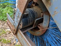
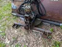
So here it is. Definitely a "project" and I knew that when I bought it for cheap. Got it off a farmer who said he was the second guy to own it and not get around to fixing it up. So I told him "Guess I'll be the third then." :) That was a year and a half ago... But I am getting a start on it and trying to move it along and figure out some of the puzzles along the way.
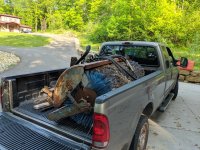
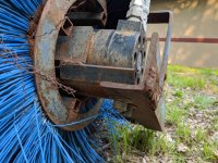
Sweepster_initial (1) (Large).jpg

Sweepster_initial (15) (Large).jpg

Sweepster_initial (16) (Large).jpg

Sweepster_initial (17) (Large).jpg

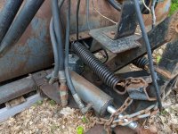
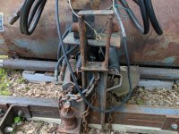
It is hydraulically driven, so I need to set up a PTO pump for it as the internal tractor hydraulics are not sufficient to handle this. More on that later. It had an unusual mounting setup that I think was modified for a 3-point. It does pivot left to right hydraulically
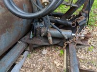
Sweepster_initial (14) (Large).jpg

It does that via this 12v electric diverter situated up on the mount that diverts a little flow momentarily when you press a switch.
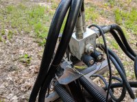
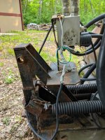
Sweepster_initial (11) (Large).jpg

Sweepster_initial (12) (Large).jpg

I need to figure out what works and what doesn't - mainly the hydraulic motor and the diverter. All the hoses need to be replaced, but it will all need to be re-plumbed in any case as I set it up on a SSQA plate for my FEL. I was thinking of using my 3rd function to drive the angle cylinder but decided that the diverter makes more sense as it is less stuff to connect and all the bits are already there. Of course I need to make sure it works first, or fix it. The motor is probably the bigger concern as it would be very expensive to replace, but I can't dig into that until i can drag this inside and tear it all apart as it is mounted to the brush assembly, so that all has to come off first. I have the owners manual and parts diagrams from the manufacturer who has been very helpful answering questions and sending that manual PDF along, so that helps a bunch on figuring things out.

And a few more final photos of the mount/pivot system
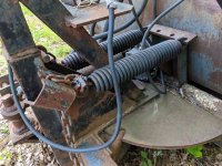
Sweepster_initial (10) (Large).jpg

Sweepster_initial (9) (Large).jpg

Sweepster_initial (13) (Large).jpg
 
   / Sweepster Rotary Broom - rebuild and modification
  • Thread Starter
#2  
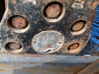
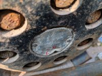
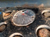
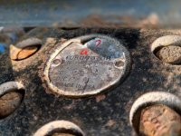
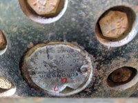
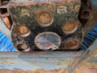
So the motor. It has a tag on it, but is bloody difficult to read due to corrosion and physical damage over the years. i found out from the tag on the sweeper and the manufacturer that it was built in 1997. I have done some looking into the motor, but it was right after I got this and I can't find that info anymore, so I'll have to try again on that. Here are some photos of the tag on the motor. I took several as I could not make out much from it, and it is not easy to get a good shot.

Sweepster_motor_tag (Large).jpg

Sweepster_motor_tag2 (Large).jpg

Sweepster_motor_tag3 (Large).jpg

Sweepster_motor_tag4 (Large).jpg

Sweepster_motor_tag5 (Large).jpg

Sweepster_motor_tag6 (Large).jpg


Here's the best I could figure out from the tag:
P/N MB122(?)108 AAAN
CC MB280 (230??)
D/C 225 97 1 (unsure on most of this)

As I said, I did find info previously that looked correct, so I probably just need to do more detailed searching to track it all down again, but I'm certainly willing to take a short cut if someone knows where to look already.

Manufacturer told me it needs 12- 25 gpm at 2000-2500 max psi. The manual says 12 gpm at 2000 psi, so apparently it has a little headroom. I'm not real sure how to test it out as I don't have anything to hook up to it yet, really. I might be able to cobble something onto my third function for a quick check but can't run that very long. Rear remotes are another test option, I guess. Well I'm taking suggestions there too, but as noted, that won't come out until warm weather for any testing.

So how am I going to drive this? Well I pretty much have 2 decent options - Rear PTO pump and Mid PTO pump. I don't currently have a Mid PTO, but it is a fairly easy install on this series with cab as you just pull off a cover on the bottom of the tranny and bolt the mid PTO assembly in there as the internal gear is already in place for it. It comes as a "whole goods" unit L8338 for ~$400. To do that, you need to drain the fluid. I am at 330 hrs now and the schedule says 400 hrs for fluid change, so I might as well just do the change at the same time. That would also be in the spring so after more plow time this winter I might be up to 350ish or so depending on if we get any real snow (blizzard at the moment but nothing since Oct otherwise).

I keep a rear blade on for main snow plowing and that will stay so it makes the rear PTO more difficult to deal with, plus routing lines that length of the tractor. I kind of ruled out the rear PTO for the difficulties it would add, but I could come back to that option if need be. If I add the Mid PTO I need to run a driveshaft to below the front grill guard where I can mount the pump. This driveshaft is tricky as it is an odd spline. The manual says it is "USA No 5 (Kubota 10-tooth) involute spline", but I can find no reference/specs for that so far. Need to dig out my Machinery's Handbook after the First when I am in the office again. Basically I need to figure out this shaft and then all I need to do is hook the sweeper on the SSQA mount and bolt the pump with 2 bolts to a mount with the driveshaft and good to go.

Next post on that drive shaft...
 
   / Sweepster Rotary Broom - rebuild and modification
  • Thread Starter
#3  
So the pump and how to drive it.

So a first big question is what about this driveshaft? I did find some old TBN threads regarding the spline, but need to do more research on that. I also suspect it will need to have universal joints on it and some type of Lovejoy or other flexible coupler to the pump, and might even need intermediate support bearings but this is a new area to me so I need to start digging into this more.

Here are a couple old threads on the Mid PTO spline
https://www.tractorbynet.com/forums/build-yourself/398080-kubota-mid-pto-spline-adapter.html

Post #114 shows another style of Mid PTO pump on a BX
https://www.tractorbynet.com/forums/hydraulics/239712-bx25-mid-pto-pump-bust.html

But also in amongst those threads was a link to a driveshaft resource:
Weasler Domestic Tractor Yoke, 6 Series Spring-Lok, .98"- 1 Spline

This looks like it might be the right spline on the one side, but it might be best to have them build a complete shaft for me (or another outfit like them) once I have it all figured out with dimensions.

For the pump I have been looking to Surplus Center at units like these
1.95 cu in Dynamic GPF232PC Hydraulic Pump | Gear Pumps | Hydraulic Pumps | Hydraulics | www.surpluscenter.com
1.52 cu in Dynamic GPF225S9C Hydraulic Pump | Gear Pumps | Hydraulic Pumps | Hydraulics | www.surpluscenter.com

And a pump mount like:
https://www.surpluscenter.com/Hydra...e_no=1&fq=ATR_Pump_Mount_Size:2\+bolt\+SAE\+A

Perhaps a spline shaft on the pump would be just the ticket to match on the free end of the driveshaft. And I need to figure out CW vs CCW as I have no idea which way the Kubota turns yet.

So that's where I am at now, just needing more digging/info on the driveshaft/pump and the sweeper hydraulic motor to move this along. And test out that diverter a bit this winter.

Updates as things come along...
 
   / Sweepster Rotary Broom - rebuild and modification
  • Thread Starter
#4  
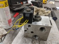
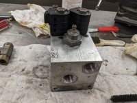
Got a bit more done. Tore apart the diverter valve to get it cleaned out and checked out. I used my DC power supply to try out the solenoid valves, and both valves look to be operating properly. They both take about 2A at 12V and the valve core moves on both when the coil is powered, so it looks like those are set. Got them pretty well cleaned up too, inside and out:

Diverter (1) (Large).jpg

Diverter (2) (Large).jpg

That thing with the set screw sticking out of it is the flow divider so only a little flow goes to the angle cylinder to avoid overpowering it and slamming it around with no control. That valve looked good too, when I pulled it. So one big win on the diverter being functional. The motor will be the other big one to watch, but that will be later on a bit.

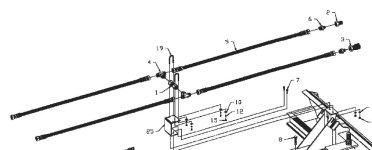
I also took apart the supply and return hose assy that came with it to figure out the crossover that was in place. Item #1 in this drawing from the manufacturer is a check valve, as it is called out.

Hose assy.jpg

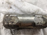
One of those hoses is supply from the pump while the other is return to tank. I know they say to limit the pressure to 2000 psi in the manual, so I am expecting this thing to be set to 2000 psi. But once I see the markings on it and look it up:

Check valve (Large).jpg
It says it has a cracking pressure of 65 psi (thus the -65 in the number), not adjustable. Anyone have any ideas to explain this? If it was a relief valve with a 2000 psi setting, that would be expected, but this seems very odd. Unfortunately I forgot to mark the orientation/direction before I took it off, so that doesn't help either. Might be time to call them again...
 
   / Sweepster Rotary Broom - rebuild and modification #5  
That check valve is there to allow the broom to free wheel or run down when the hydraulic flow is stopped by the control valve. System relief valve would typically be the first valve from pump outlet frequently located in the directional control valves
 
   / Sweepster Rotary Broom - rebuild and modification
  • Thread Starter
#6  
Interesting. So then it is probably plumbed in pointing to the pressure supply line from the return line to maintain that flow loop. That makes sense and something I hadn't even considered.

And thanks for the reply. I was beginning to think I had written the most boring thread on TBN with zero replies after 400+ views :confused3::laughing:
 
Last edited:
   / Sweepster Rotary Broom - rebuild and modification #7  
Check valve would be plumbed to prevent flow from pressure to return line and allow flow from return to pressure.

No easy way to test the motor that I know of other on test bench or real life use. I am not very familiar With the torqmotor but it is possible the CC is displacement in cubic centimeters per revolution. Multiply cc by .06102 to calculate cubic inch per revolution

Very common for European manufacturers to use CC for displacement.

Mid PTO works if you have a place to mount the reservoir and associated components. That is frequently the biggest challenge
 
   / Sweepster Rotary Broom - rebuild and modification
  • Thread Starter
#8  
Check valve would be plumbed to prevent flow from pressure to return line and allow flow from return to pressure.

No easy way to test the motor that I know of other on test bench or real life use. I am not very familiar With the torqmotor but it is possible the CC is displacement in cubic centimeters per revolution. Multiply cc by .06102 to calculate cubic inch per revolution

Very common for European manufacturers to use CC for displacement.

Mid PTO works if you have a place to mount the reservoir and associated components. That is frequently the biggest challenge

Yep, we are saying the same thing on the check valve. Thanks for that.

I am going to put all hydraulics including the tank on the FEL on a SSQA mounting plate. The pump will be on hoses so it can be attached to the PTO shaft that comes out at the front of the tractor.
 
   / Sweepster Rotary Broom - rebuild and modification
  • Thread Starter
#9  
I did finally get the motor pinned down. It was a Ross/TRW Torqmotor which is now owned by Parker (like everything hydraulic...) and the part number I read was correct as best I can tell: P/N MB122108 AAAN. I wasn't able to pin down the last letter N in the options as it doesn't match up in their tables, but I think it means a castle nut with cotter pin, so the current match would be: Parker TF0195WB080AAAF That last letter option isn't real critical in any case.

Took quite a bit of digging to sort that out. A lot more than one would expect as they should want people to make easy cross references for old parts.

Not the most important thing to figure out, but all I can do right now with it buried under a foot of snow and it may become helpful down the road. I won't know it is all correct for sure until I can pull it apart when it warms up.
 
   / Sweepster Rotary Broom - rebuild and modification
  • Thread Starter
#10  
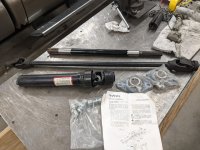
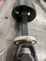
And one more piece of the puzzle falls in place. I managed to find the L2183 Mid PTO driveshaft assembly at a dealer in NJ via eBay for a decent price, so was able to pick this up:

Mid PTO driveshaft (1) (Large).jpg

So that allows me to go from the Mid PTO to the front of the tractor. I need to get the Mid PTO kit and install it so I can get this fitted and start to figure out where this comes out in the front so I can plan out the pump mounting and how to adapt/extend the pump to the driveshaft.

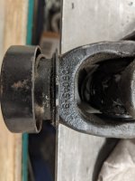
And for anyone looking to attach to the mid PTO, the end shown below is it. Cast into the yoke is Weasler on one side and this number 06045-9 on the other side, so it should be available from suppliers who carry Weasler driveline parts.
Mid PTO driveshaft (2) (Large).jpg

The part below is the output shaft that would drive a snowblower or other Kubota implement. It attaches to the front of the mid carrier shaft with a common 1-3/8" 6 spline PTO yoke. The free end is a 3/4" x 7/8" solid rectangular shaft. I may either change that free end out for something different or just adapt to it with the pump. Need to get that PTO in place to see how this all shakes out in space on the tractor first!

Mid PTO driveshaft (3) (Large).jpg

As I was looking at that output shaft yoke thinking of changing it out I realized I have no idea how they get universal joints together. They look like something impossible to assemble. My only guess is that the arms of the yoke are somehow spread apart to get the U-joint in and then snapped back in place on them. I imagine that is a pretty high-force task, and one I am not surely equipped to do...
 
 
Top