scott_vt
Super Member
- Joined
- Oct 5, 2004
- Messages
- 7,771
- Location
- east wells,vt
- Tractor
- 1986 MF 1040, 1942 Farmall A, 1949 Farmall Super A
Mornin Larry,
Looks like you have come up with a great idea ! And with Robs help Im sure it will turn into reality ! Glad to see you guys hooked up and put your collective minds to work together !
Reading through the thread, I thought I was serving my apprenticeship allover again")
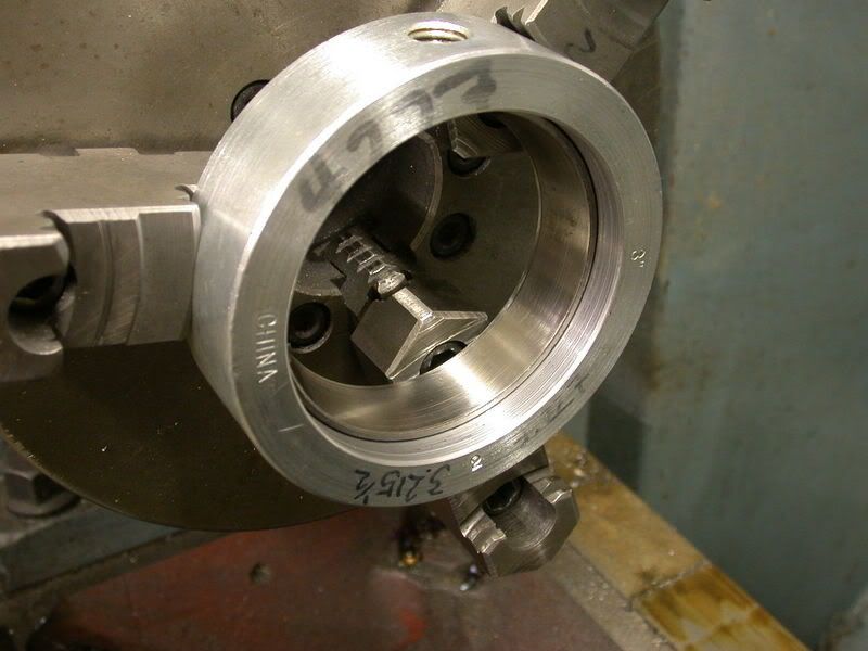
One question on the keyway you broached. Couldnt you find anyone with a hydraulic press ? All you really needed to do was make a plug to fit the bore on your lathe, mill a keyway through the plug and use a keyway broach with shim stock for progressively deeper cuts !
Great thread, and I will be following along!
Looks like you have come up with a great idea ! And with Robs help Im sure it will turn into reality ! Glad to see you guys hooked up and put your collective minds to work together !
Reading through the thread, I thought I was serving my apprenticeship allover again
One question on the keyway you broached. Couldnt you find anyone with a hydraulic press ? All you really needed to do was make a plug to fit the bore on your lathe, mill a keyway through the plug and use a keyway broach with shim stock for progressively deeper cuts !
Great thread, and I will be following along!