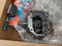
Sweepster Rotary Broom - rebuild and modification

   / Sweepster Rotary Broom - rebuild and modification #11  
View attachment 683020
As I was looking at that output shaft yoke thinking of changing it out I realized I have no idea how they get universal joints together. They look like something impossible to assemble. My only guess is that the arms of the yoke are somehow spread apart to get the U-joint in and then snapped back in place on them. I imagine that is a pretty high-force task, and one I am not surely equipped to do...

If you look in the inside of the yoke there is a grove with a circlip in it. Remove the circlip and carefully take the joint apart. There is probably a good YouTube on how to take it apart and put it back together. If you can't find anything then pm me and I can walk you thorough the process by phone.
 
   / Sweepster Rotary Broom - rebuild and modification
  • Thread Starter
#12  
Huh. Yeah a little time on da Youtube was all it took. I had no idea how those went together as I have just never had to deal with one before. Actually much easier than I was expecting. I figured the bearings on the cross were permanently mounted to it but they are not and it just comes apart. Thanks.
 
   / Sweepster Rotary Broom - rebuild and modification #13  
No problem. The trickiest part that I have issues with when putting them back together is not having the needle bearings inside the cup fall over. When I took my heavy duty schooling they told us to put a shot of grease in the cup and spread it all over the needles. This was to make sure that all the needles had lube before you put the joint back together, but I found it sure helps to keep needle bearings in place as you fiddle everything back together.
 
   / Sweepster Rotary Broom - rebuild and modification
  • Thread Starter
#14  
Thanks. Yeah Youtube said many of the same things about the needles. The bit about adding grease makes perfect sense too. I looked at what I have in this yoke assembly and they have clips on the inside of the joint. May not be as easy to get to, but I know what to do now. Are you also on Welding Web with the same handle...or Practical Machinist? I know you have been here a long time but your tag sounds familiar from elsewhere, too.

So I may have finally found a decent solution to the problem of mating the pump to the driveshaft. I asked about suppliers of spline parts on PM and one of the replies was for these guys:
G&G Manufacturing Company
They have a decent catalog with a lot of options. It helped me learn and sort through the world of driveshafts and adapters (which as you can see I am new to). Well they have this system Called "Weldajoint" or something that allows you to build up a shaft from components if you just weld together the various items. More importantly they have a hub adapter system that might solve all my problems. They list a ton of bushings for all sorts of shafts that can be welded to their hub adapter so you can mate 2 different shafts pretty easily.

So this looks like the bushing that will fit the pump's 13 tooth spline (ignore picture, it is a different configuration, but just gives the idea):
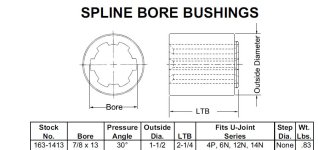
Spline bushing GG.jpg

Then I get the first coupler/hub in this table:
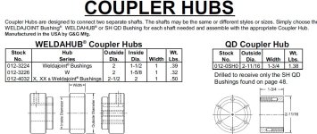
Coupler GG.jpg

And then just figure out what I need on the other side of the coupler hub and weld it all up. Best case I can use the 3/4x7/8 shaft on the driveshaft right now. Worst case it does not reach and I replace that half of the yoke/shaft with something that does reach and use that. Kind of an important weld as I don't have anything to try it out on first to set parameters and I am not some pro welder, so I need to dial things in first, but I bet I can get there.

I am also thinking of a bearing at the end to support the end of the driveshaft where it meets the pump. But that is a ways off for now. Just one of the many things taking up space in my head about this...
 
   / Sweepster Rotary Broom - rebuild and modification #15  
Thanks. Yeah Youtube said many of the same things about the needles. The bit about adding grease makes perfect sense too. I looked at what I have in this yoke assembly and they have clips on the inside of the joint. May not be as easy to get to, but I know what to do now. Are you also on Welding Web with the same handle...or Practical Machinist? I know you have been here a long time but your tag sounds familiar from elsewhere, too.

Watch when you pull the clips out that they don't go flying somewhere where you can't find them.

I'm not on any of the other sites mentioned. I would like to be but I already spend too much time on the internet.
 
   / Sweepster Rotary Broom - rebuild and modification
  • Thread Starter
#16  
Thanks. Yeah the Youtubes pretty much covered that the clips on the internal versions can fly like crazy so wrap a rag around it first. Your tag looked similar to others I have seen so thought it might be you. No biggie, just curious.

I think I have the adapters for shaft to pump figured out now. Next, need to get the Mid PTO and install it (and change fluid & filters at the same time...) and then I can seriously start looking at how to support the driveshaft bearings and see what I need for the front part of the shaft to connect to the pump as far as lengths etc. I should be able to order the Mid PTO, fluid, filters next week and then can work on doing it over the next couple months before it gets warm out. As long as it doesn't interfere with snow plowing, but it has been a light winter for snow so far.
 
   / Sweepster Rotary Broom - rebuild and modification
  • Thread Starter
#17  
And what do we have here?

Mid PTO gear.jpg

Well that looks like a Mid PTO gear kit, Dave! You know, Dave, I think you're right!

That came in a few days ago along with the hydraulic filters for the tractor. I'll get fluid locally as shipping was way high on fluid (adds 40-50% of the actual fluid cost). Since I have to drain the fluid, I'll do the 400 hr service early. I only have 330 hrs now, but might as well. It will still probably be 3-4 weeks before I get to the fluid and PTO install. Looks to be getting super cold for the next couple weeks, so I will wait until after that at least. No rush as the serious rebuild work can't start until it warms up and dries out.
 
   / Sweepster Rotary Broom - rebuild and modification
  • Thread Starter
#18  
Progress... Got the fluid and filters changed and the Mid PTO installed the past couple evenings. Was not too bad but if I ever get my hands on the idiot who taped the connector for the switch up under the seat, I will strangle him. Spent over half an hour ripping apart the wiring harness in the relevant area to find it with no luck. Decided to pull the seat to get a view from above. I hate pulling the seat as it weighs 5000 lbs (BTDT). Found I could break it into 2 pieces relatively easy so that helped a lot but still that is awful to get in there. So I pull the seat, and there is the connector staring at me - well hidden where you cannot get to it without pulling the seat. grrrr. But it's done and works fine.

I wanted to run it and take a look so I could see which way it spins, but apparently the mode where you flip the seat forward only works on the rear PTO. If the Mid is engaged, it kills the engine. So I put my phone on video record, slid in under the PTO and sat in the seat to run it. I find out at idle it spins about 700 rpm, and at max throttle 2100, so the 2000 rpm rating is right near the top of the engine limit. And as best I can tell from the video, it spins CCW if you are facing straight at the free end of the PTO shaft.

Next up will be sorting out the driveshaft. I have to see how far it reaches and where i can attach the bearing supports.

Pics installed...
Mid PTO installed (1) (Large).jpg
Mid PTO installed (2) (Large).jpg
 
   / Sweepster Rotary Broom - rebuild and modification
  • Thread Starter
#19  
Got stuff cleaned up and played around with the driveshaft a bit tonight. So I got the drive shaft together and in place to get a look at it. Below are a few photos. The shaft comes out real close to where I would like it to. If it was a few inches longer, then I know for sure it would be plenty long and could be cut to length if needed but this may very well work ok as-is. The end of that square shaft is right about where that right-hand hole in the orange grill guard is (hard to tell in photos) which is approx 3" in from the front of the guard, in the third photo. Worst case, I buy a new shaft section with yoke end that is longer and I cut it to length - and I know a source of those already if needed. You can see the PTO gearbox on the far right in the first picture.
Mid PTO drive shaft (2) (Large).jpg

Mid PTO drive shaft (4) (Large).jpg

Mid PTO drive shaft (1) (Large).jpg


Below - That middle shaft that is black with the 2 ends bare metal is where the bearings go (on the bare sections). It is the section held up by the red jack stand on the left. That jack stand is on one of the 2 bare sections where one bearing will go.
Mid PTO drive shaft (3) (Large).jpg


They also came with the kit, but I need to figure out mounting since I don't have the whole subframe that the front mounted blower would normally have to mount them in. I have a pretty good idea how I am going to approach that, in general terms. The jack stands were "close enough" on height but not perfectly aligned. I may need to do something else to get it set perfectly for laying out the supports. Maybe just big shims of various thickness plywood below the stands. The shaft centerline sits about 13" above the floor, approx.

If anyone has any bright ideas on supports, I'm all ears. Other than those 2 bearings it has no other supports as of yet, so I will need to sort out what else it needs. The PTO end should be OK as this mimmicks the snowblower kit back there, but I will probably have to support the free end of the solid shaft that will drive the pump with another bearing of some sort.
 
Last edited:
   / Sweepster Rotary Broom - rebuild and modification
  • Thread Starter
#20  
Got back under there with a tape measure and some scraps of hardboard to see what I could sort out. I'm sticking with a sort of ladder frame around it and to support the bearings. Similar in concept to the Kubota snowblower mount/frame but a bit more customized for this application. Go back earlier in the thread if you want to see diagrams of Kubota's frame. I then roughed it out in CAD, easy for me since that is a fair part of what I do for a living, to give me a better 3D picture. The screen shot below is that. Dimensions are fairly rough/approximate but I am mostly just trying to visualize here and see anything obvious.

I picked 3 mount points - rear, middle and front. In the CAD pic, the yellow part is a rough mock up of the shaft, with the thicker sections being the universal joints between the sections, and where it sticks out is in the rear that connects to the PTO gear. The end with the hole in it is the front where another support bearing will go and where the pump will attach. The bearings that came with the kit go on the middle shaft, just inboard of the joints. I found a couple unused tapped holes in the bottom of the tranny housing that should work for the rear mounting point. Up front, I will use those 2 holes on either side of the grill guard from the photos in the previous post to bolt up to and in the middle I will use a bolt or two from the loader front mount shown below. The lowest ones. I will need to get a couple longer 8.8 M16 bolts for the mid mount, but no biggie. Not sure if I will add any crossbars on the top of the channel like the bottom has, but I will probably do a couple to help make it more rigid.

Loader front mount.jpg


PTO_mount1 CAD.jpg
 
 
Top