360* Rotating Back Blade Project

   / 360* Rotating Back Blade Project #61  
After all that, I took the collars and clamped them into the bored holes in the plates. They are also a slight press fit. I was thinking of heli-arc welding them in place but may not need to do that? So I stamped the plates and the collars to identify which one goes where in case Larry ever takes it apart, he will know where every single component goes. Unless I weld them in place of course. But I had to tap them with a mallet to get them to seat while clamped like this.


So to make a short story long, here are the top and bottom plates, complete 100% finished. The thrust bearings and hollow splines are in them too.


Stay tuned for what happens next ... uh ... I have to figure out what's next? Probably the side plates.
 
   / 360* Rotating Back Blade Project #62  
I have more photos of the side plates that will hold the hydraulic motor and worm itself. You've seen the roughing cuts I made on the other plates and this is more of the same. Here I'm taking ½ the width of the rough mill at .250" deep. This roughing rotary milling goes real slow.


Exactly how slow? Well, this video shows how I have to hand-over-hand move the rotary table dial to feed the roughing end mill. I'm taking the full width of the cutter this time. The cutter is buried .250" deep and going 170 rpm. I don't know if you can see or not, but during this (approx 1 minute) video, the table rotated 12°. That means at this rate in order to do one revolution, it takes me 30 minutes of handle turning like that for each pass I make.


So roughing on the rotary table is a PITA but you have to do it not to lose control or knock your work piece out of location due to shock....hold on to that handle tightly and move it at a consistant pace.
Now this video shows finishing the bottom cut. This is a 2 flute solid carbide endmill spinning at 1200 rpm and taking only .010" finish pass. Now you have to kick butt turning the rotary table. I"m getting a good workout on Larry's project.

 
   / 360* Rotating Back Blade Project #63  
I added some "O" rings to seal the SHCS that hold the hydraulic motor onto the side plate. I had to drill and tap deep enough to hold the motor on and oil could get through the screw threads so now they're sealed too.
You can see the "O" ring in the front and the groove on the far one around the tapped threads. They are 1/2-13 threads, not 3/8-11 threads.


Here is the oil seal for the worm shaft getting ready to be pressed into place. that counter bore, BTW, is for the locating diameter on the face of the hydraulic motor. It ensures proper line up for mounting the motor instead of just bolting it flat to the plate. Everything will be in line perfectly and can't get out of position.


You can see the oil seal completely pressed in all the way here. I thought I'd show a close up of how the "sealer paint" on the outside of it is supposed to "melt" when the oil seal is pressed in and seal around the metal case. That's what Larry told me. Here you can see some of it on the side walls. There is is green trace of it.

 
   / 360* Rotating Back Blade Project #64  
Here is the plug I had to make for the hole I drilled all the way through the second side plate. It is "O" ringed so no leaks.


I turned it on the lathe and made the part in front of the "O" ring .001" smaller than the bore and the part behind .001" bigger for a press fit. Then sawed it off while still in the "V" block and pressed it into the plate.

 
   / 360* Rotating Back Blade Project #65  
Here it is pressed into the plate and set in my vise to mill down.


Now it is milled flat with the pocket and good to go....no more "free lightening hole". ;D

 
   / 360* Rotating Back Blade Project #66  
After the hole was plugged, it was time for milling on the round corners on the 2 end pieces so they would clear the outside radius left by the end mill in the pockets. I have a set of "corner rounding end mills" that I use for this. They are for machining clearances. Really accurate radii I would grind on the steel using the surface grinder.


After doing that, I realized I could now bolt the box together so I did and what do you know....everything fit perfectly. :confused:
So I decided to throw the worm and worm gears in there on their shafts.
Here's what that looks like.


Bet that makes Larry happy.
 
   / 360* Rotating Back Blade Project #67  
Here are a couple more pictures of it all assembled. I don't have the correct spacers in there yet, but you get the idea. There will be some fitting to do to get pre-load on the thrust bearings.


So there are all the small details to do yet but the major part is done. I decided to clamp a "V" block on so I could try it out.
It works!!!


Hope you like it so far.
 
   / 360* Rotating Back Blade Project #68  
3RRL said:
Hope you like it so far.

You look like you're having way too much fun! I've had a desktop cnc mill sitting next to my computer for a couple years now, gotta get it going. My teacher is lazy. :eek:

Monte
 
   / 360* Rotating Back Blade Project #69  
Hey Larry & Rob,

You two make one heck of a team!!! The idea is pretty ingenious, and the more I thought about it while reading the thread, the more complicated it got. I keep trying to see how it could be done with hydralic cylinders, but can't get past locking it into position. How do motor graders lock the blade in position? Is it just larger hydraulics?

The gear box and machine work is just fantastic!! So much of it is total greek to me that I'm struggling just to keep up. Figureing it all out is just beyond my metal ability. hahaha

Is the gear box going to be full of oil? How do you fill it and how full do you keep it? Regular 90 weight gear oil?

Now that you have the gear box done, I'm very interested in how it will turn the blade and how it will be controlled. This is just one of many areas that I'm coming up short and not able to figure out.

Thanks for another great post. You guys are pushing the envelope unlike anybody else!!!!

Eddie
 
   / 360* Rotating Back Blade Project
  • Thread Starter
#70  
Rob,
Excellent - It's EXACTLY what I had envisioned!
I am so super pleased with the precision and speed your turning this out. WOW! :D
I could not help but to commemorate this special milestone moment with a little thank you from the bottom of my heart:

What a great shot! Just look at that smile - He's so happy he could eat a banana sideways!
I have to wonder though if that smile is from knowing he's just about to "GET THIS THING OUT OF MY SHOP" :rolleyes: (J/K Rob's having a blast with this project - what a ham)
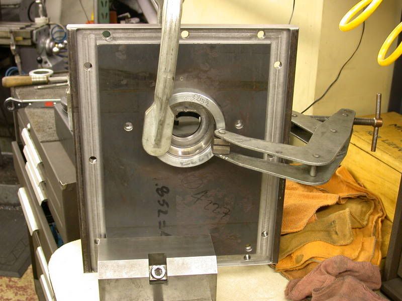
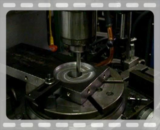
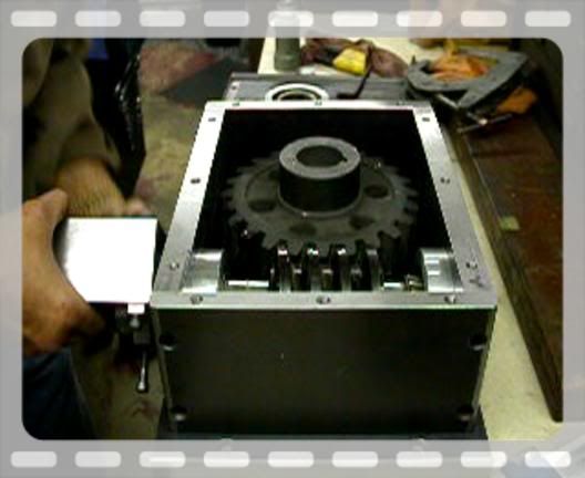
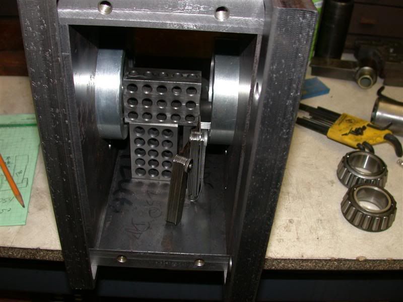
I think I ran the video of Rob rotating the gears so many times that the gears are now properly "Run In" ;)
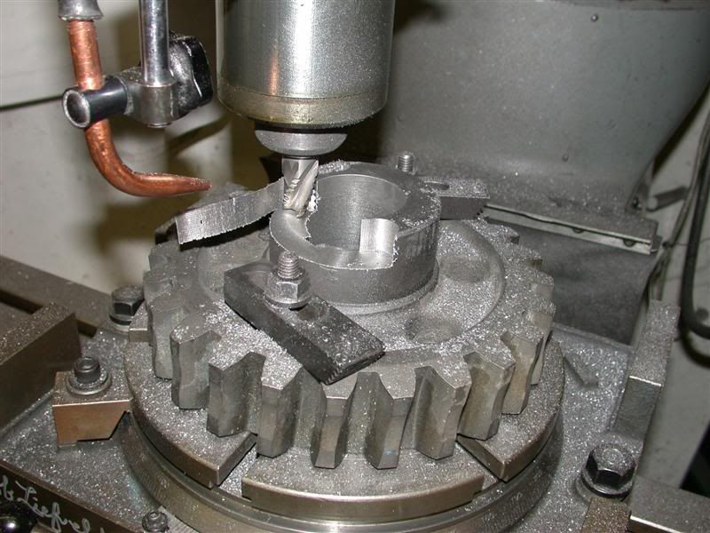
Has anyone ever noticed that nice "time peace" Rob always wears on his wrist? I can't believe he had that on while machining, Especially on the rotary table when his hands were quicker than the eye, it got SO close to the edge of that steel plate :eek:

I Imagine it will be late next week before Rob get a chance to work any more on this. I bet you'll be dreaming about it like me though.
Have a great time at camp. Tomorrow it will be three weeks since our visit together. It's amazing all you have accomplished in that short time. I bet you and Loretta are anxious to get back up to camp. You might even have blossoms on the peas in the food plot.

Have a save trip and a great time -

Larry


Eddie -
Thanks for the wonderful comments - Rob is truly amazing.
This is turning out pretty cool - huh?

Is the gear box going to be full of oil? How do you fill it and how full do you keep it? Regular 90 weight gear oil?

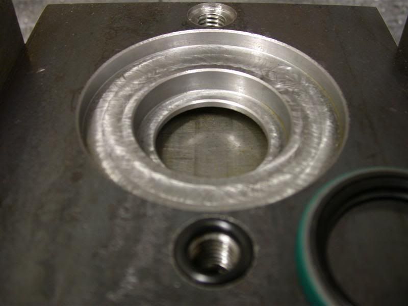
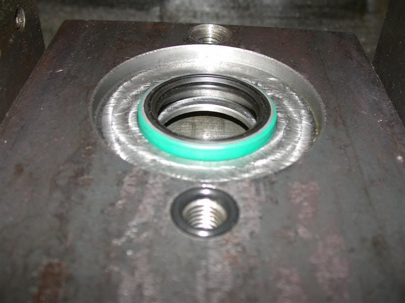
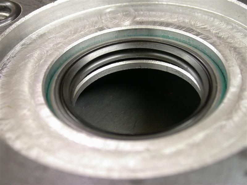
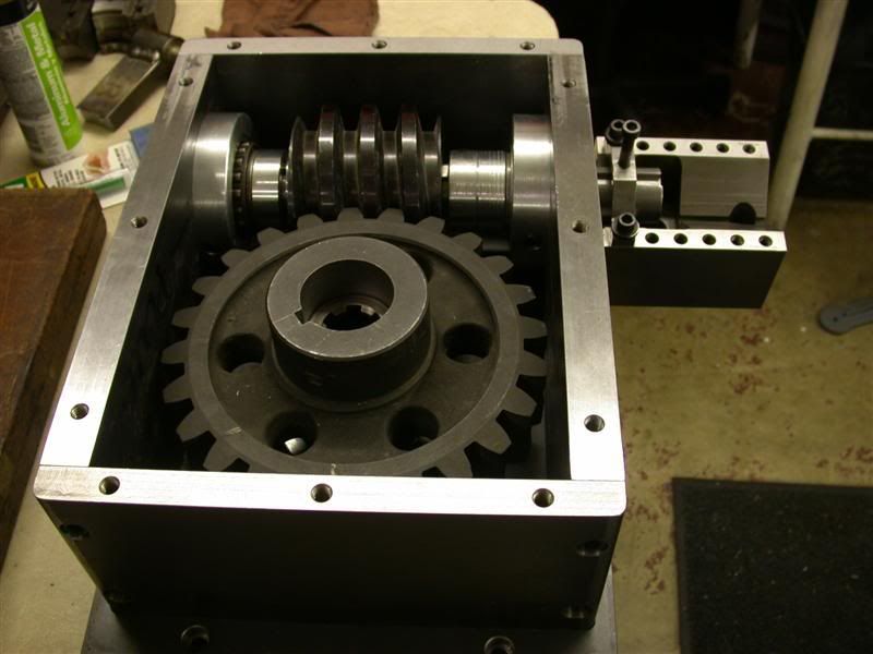
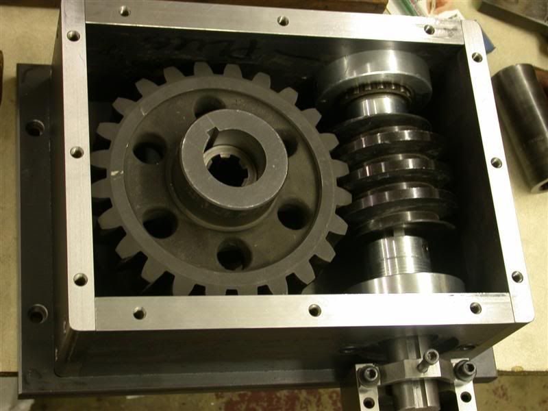
About 7/8 full of 85-90 W gear oil. I think the calculations are about 10 quarts total internal volume, minus the displaced volume of the gears, shafts, bearings and thrust washers so somewhere in the neighborhood of ~ 6 quarts. Rob put a filler and drain hole in the top & bottom plates for me.

Now that you have the gear box done, I'm very interested in how it will turn the blade and how it will be controlled.

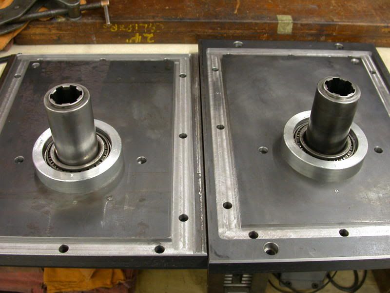
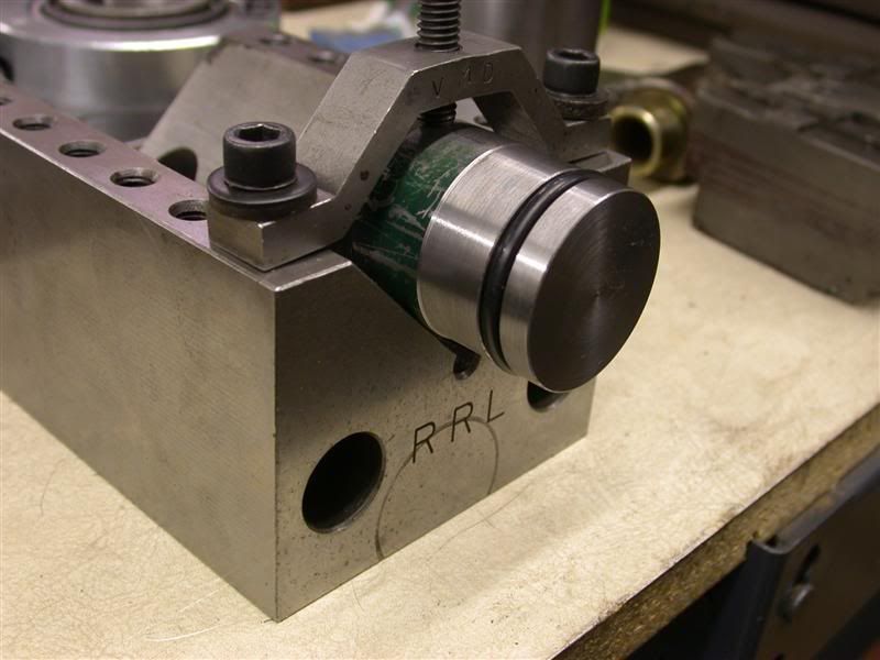
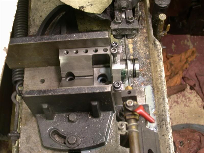
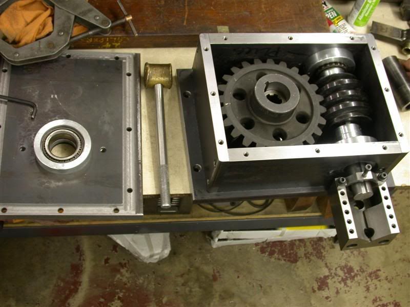
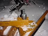
In the video where you see Rob rotating the gears by hand - There will be a hydraulic motor. I already have the control valve & hoses on my tractor ready to go. Take another look at the center shaft of the worm gear, there is a hollow 6 spline PTO shaft coupler that is going to be connected to the blade pivot shaft. Here is a pic of the blade and the PTO shaft that the Gear Box will couple to so it can turn the blade 360*. It's a slip fit between a hollow PTO coupler onto a 6 spline PTO shaft.

Just envision the gearbox sitting on top of the back blade then sliding over that coupler you see on the pivot point:


It wont be long now-

Larry
 
Last edited:
   / 360* Rotating Back Blade Project #71  
3RRL said:
Here is the plug I had to make for the hole I drilled all the way through the second side plate. It is "O" ringed so no leaks.

No grooving shots for the o-ring ? :(

WOW. Instead of setting up a shop at the new place maybe you should consider giving classes. I've got tree mills and leblond lathes and still picked up a couple of pointers from your work. Heck, when's the first class :)
 
   / 360* Rotating Back Blade Project #72  
GuglioLS said:
I am so super pleased with the precision and speed your turning this out. WOW! :D
This is turning out pretty cool - huh?
Larry

Well beyond pretty cool. This project will be fantastic when you guys are done. Rob alluded to using this setup for other attachments, well what would those be?
 
   / 360* Rotating Back Blade Project
  • Thread Starter
#73  
tlbuser said:
......" Rob alluded to using this setup for other attachments, well what would those be?

tlbuser,

Thanks for the compliments and question -
In addition to using it on the Back Blade, the Gear Box can be used on a Rock Rake, and as a PHD that's attached to the FEL, since it's powered by a hydraulic motor the auger rotation will be reversible.

Also under consideration is a Winch, Since the worm which drives the worm gear has a helical angle of 4°-16' it's a "self locking angle" (generally anything under 5°). So the worm gear will not rotate the worm, it's locked there until the motor starts to drive the worm again. This makes it a great candidate for a very powerful winch.

Larry
 
   / 360* Rotating Back Blade Project #74  
Guys,
Thanks for the compliments on Larry's gear box project. When Larry asked me to post some of the machining involved I thought it might be boring to some. Most would want to see the finished product sitting on Larry's blade with a video of how he controls and scrapes with it ... I know I want to see that too. But he insisted on the machining pictures and I'm glad you guys got a kick out of them.

tlbuser,
Thank you.
I never thought of teaching a machine class, but I have trained hundreds of apprentices in the past. I just took it for granted that it was part of my job. When I started working out of my garage in 1978, I had to be resourceful in the set-ups because I did not have all the equipment a fully tooled shop had.
When I was a kid in the sixties, I worked at a 30 man tool and die shop that had all tree mills. They were the industry standard back then rivaling Bridgeports. They were very sturdy mills. Oh, and grooving for the "O" rings ... I thought that would put you to sleep.:D

Like Larry mentioned, I will be busy doing a bunch of other things for the rest of the week and going up to my camp. But after that, I will set all the spacers and finish the keyed shafts for both worm and worm gear. Last will be attaching the hydraulic motor to the shaft in a manner that Larry can take it on and off easily for maintenance and sealing the box. I'll post more next week.
Thanks again,
 
   / 360* Rotating Back Blade Project #75  
3RRL said:
So I decided to throw the worm and worm gears in there on their shafts.
Here's what that looks like.


Bet that makes Larry happy.

Afternoon Rob,
Hhmmmm, looks very similar to the steering box on my Super A, except its not a round casting ;) :)

Hey do you want to subcontract some of that milling work ? Ive got an Anilam 3200 controled Bridgeport that should be able to reduce that rotary work !;)
 
   / 360* Rotating Back Blade Project #76  
scott_vt said:
Afternoon Rob,
Hey do you want to subcontract some of that milling work ? Ive got an Anilam 3200 controled Bridgeport that should be able to reduce that rotary work !;)
Scotty,
I would love to do that but you'll have to work for the same rate I get from Larry.:D Nice of you to offer though, thanks. I do have access to two large shops out here that are fully equipped, but I had the old rotary table so I just did it in the garage. At one time I even considered bolting them to the face plate and turning them on the lathe. I would like to get one of those Anilam controllers for one of my mills. It would certainly come in handy.
Rob-
 
   / 360* Rotating Back Blade Project #77  
After getting Fergie all settled at her new home, I got to work on Larry's gear box some more. I needed to position the worm so it would be centered between the 2 thrust bearings and also be located at the exact tangent of the big worm gear. I had to re-assemble the sides of the box which holds the worm.
So first I clamped the thrust bearings into position by using jack screw technique.


Then I measured the space inside with gage blocks and feeler gages until I thought is was tight enough. That gave me the actual dimension between the thrust washers and I added .002" for pre-load.


Then I subtracted the length of the worm and ground the spacers equally to center the worm.


In order to assemble the sides with pre-load, the side plates cannot be bolted to the ends yet. They have to be clamped together and then the ends are bolted on and the box is tapped into the pocket in the bottom plate. Now it is tight in there.
 
   / 360* Rotating Back Blade Project #78  
Then I had to do the same thing for the big worm gear. Except it is held in position by the top and bottom plates. I had to take apart the sides and bolt the sides into the top plate and then into the bottom plate because of the pockets in them. In this case, I took some preliminary measurements to get my gage block dimension close.


Then I bolted the top and bottom plates together on the side plates which will determine the distance between those thrust washers. I went through the same process to get my dimensions which will now position the big worm gear in the center of the box. I also added .002"pre-load to this dimension.

 
   / 360* Rotating Back Blade Project #79  
Centering the big worm gear meant cutting off part of the hub projection. I am not wasting any time on sissy milling cuts anymore so I took a Ø3/4" corn cob mill and buried it 3/4" deep at full width cut. Then ground the height of the hub to the correct dimension. I also turned the spacer for the other side and ground it also.


Here is the big worm gear now captured and centered correctly between the top and bottom plates. Man, this gear box is really heavy with just the side plates and top and bottom plates. It still will have the shafts, worm and hydraulic motor on it before it is done. LOL ... It is going to weigh a ton with 10 quarts of oil in it!


Tomorrow I will start connecting the hollow splined shafts and start the shaft work for the worm and hydraulic motor. Larry's gear box is nearly complete now.
 
   / 360* Rotating Back Blade Project #80  
Mornin Rob & Larry,
Nice progress ! Im really enjoying this thread ;) for a couple of reasons really !

1st its really interesting !

2nd I think its great that so many people are interested in machining ! When I got into the trade 35 years ago, people would say, so what trade are you in ? And I would tell them toolmaker/machinist, and they would say "ohhh you do that" :( :confused: Fast foward 35 years and somebody is actually interested in working metal :)

Keep the posts and pics coming, Im feeling important again ! ;) :)
 

Tractor & Equipment Auctions

2016 UTILITY 53X102 REEFER TRAILER (A59905)
2016 UTILITY...
John Deere TX Gator (A60462)
John Deere TX...
SCREENER (A58214)
SCREENER (A58214)
2012 GENIE Z-45/25J ELECTRIC BOOM LIFT (A60429)
2012 GENIE...
2019 KUBOTA SVL75-2 SKID STEER (A60429)
2019 KUBOTA...
3015 (A56857)
3015 (A56857)
 
Top